


4 OM-CFK-20
ELECTRICAL
Probe Resistance
500 Ohms ± one percent in a stirred ice bath
No-Load Running Current
110/115 Volts
1.8 Amperes
220 Volts
1.0 Amperes
Full-Load Running Current
110/115 Volts
2.5 Amperes
220 Volts
1.3 Amperes
Motor Speed
60 Hz
1500 RPM at full load
50 Hz
1250 RPM at full load
Agitator Speed (No-Load)
60 Hz
50 RPM
50 Hz
50 RPM
Motor Start/Circuit Breaker
Trip Current
110/115 Volts
1.75 Amperes
220 Volts
1.35 Amperes
Over-Temperature Switch
Opening Temp
195ºF ± 6ºF
Heater Power 110/115 Volts
& 220 Volts
1850 Watts
MAINTENANCE
WARNING: SHUT OFF THE ELECTRIC POWER TO THE UNIT BEFORE YOU OPEN THE
BOTTOM COVER.
WARNING: TO AVOID INJURY, READ AND FOLLOW ALL PRECAUTIONS STATED ON THE
LABEL OF THE WATER TREATMENT COMPOUND.
WARNING: BEFORE REPLACING ANY PARTS, DISCONNECT THE UNIT FROM THE
ELECTRIC POWER SUPPLY.
NOTICE: Contact an authorized representative when repairs are required.
PERIODIC MAINTENANCE
A Maintenance & Service Log is provided at the back of this manual. Each time
there is maintenance performed on your Groen kettle, enter the date the work
was done, what was done, and who did it. Keep this manual on file and available
for operators to use. Periodic inspection will minimize equipment down time and
increase the efficiency of operation. The following points should be checked often:
1. The jacket water level should be at the middle of the gauge glass when the
kettle is at room temperature. If the level is low, see “Jacket Filling”.
2. The inside of all housings should be kept clean and dry.
3. Electrical wiring should be kept securely connected and in good condition.
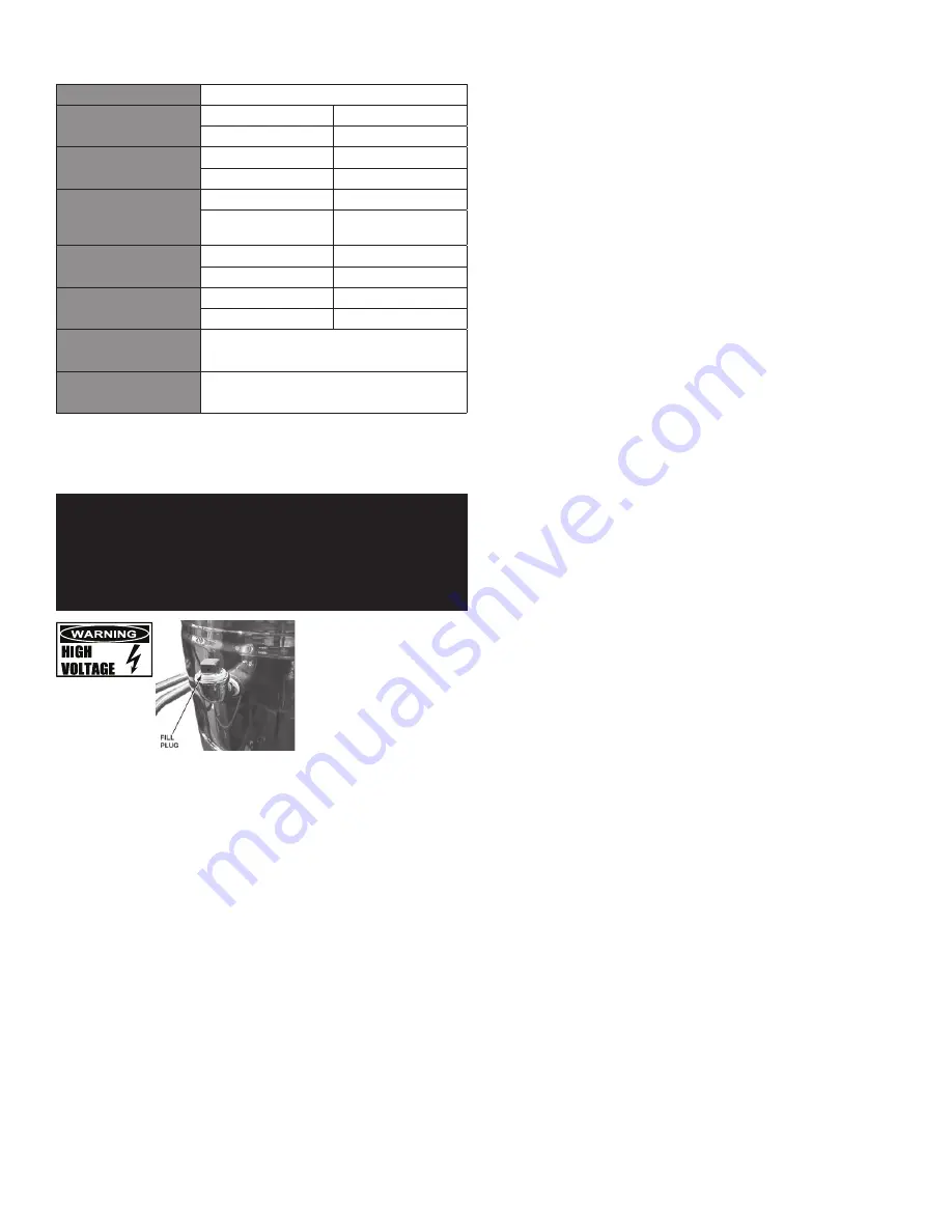
4. The fill plug on the elbow at the back of the kettle should have vent holes in it.
These holes must be kept free of debris for proper venting. Plugging the holes
could cause pressure to build!
JACKET FILLING AND WATER TREATMENT
The jacket must be kept filled with the proper amount of treated water. From time
to time, you will need to restore the jacket water to the proper level, because its
water slowly evaporates. You may also need to replace treated water, if the jacket
is drained for any reason. The procedure for adding water follows:
1. If you are replacing water lost by evaporation, use distilled water. If you are
replacing treated water that ran out of the jacket, prepare more treated water
as directed below.
2. Remove the plug from the elbow on the back of the kettle body. Note the
venting holes in the image above.
3. Add water or treated water through the elbow, until the water level rises to the
middle of the sight glass. Since the water you are adding must raise the level
in the whole jacket, a substantial amount of water is needed to make a small
change in the level.
4. Replace the plug in the elbow.
WATER TREATMENT PROCEDURE
Obtain water treatment compound and a pH test kit from your supplier, or directly
from your Groen Parts Distributor.
1. Place exactly one gallon of water in the mixing container. Distilled water is
recommended.
2. Hang a strip of pH test paper on the rim of the container. Allow about one inch
of the strip below the surface of the water.
3. Measure the water treatment compound you will be using. (One way to do this
is to add the compound to the water from a measuring cup.)
4. Stir the water continuously, while you slowly add water treatment compound,
until the water reaches a pH between 10.5 and 11.5. Judge the pH by
frequently comparing the color of the test strip with the color chart provided in
the pH test kit. Color blind people mixing the treated water solution must use
an electroanalytical instrument to measure pH or have a person who is not
color blind check the test strip color level.
5. Record the exact amounts of water and treatment compound used. These
amounts may be used again, if the same sources of water and compound are
used to refill the jacket in the future. However, it is advisable to check the pH
every time treated water is prepared.
COMPONENT REPLACEMENT
Internal wiring is marked as shown on the circuit schematic drawings. Be sure that
new components are wired in the same manner as those being replaced.
REPLACEMENT PARTS
To order parts, contact your Authorized Service Agent. Supply the model
designation, serial number, part description, part number, quantity, and when
applicable, voltage and phase.
CONTACT US
If you have questions pertaining to the content in this manual, contact Unified
Brands at 888-994-7636.


