Model T27417 (Mfd. Since 09/15)
-19-
1. DISCONNECT MACHINE FROM POWER!
2. Remove spindle sanding components
in reverse order of installation (see
Figure 17 on Page 18).
3. Clean openings for table insert, throat plates,
and any other spindle areas as necessary.
There should be no sawdust on ledge of table
openings where table insert and throat plates
are placed or these components will not sit
flush with table.
4. Use sizing table on Page 18 to select required
size of components for sanding drum/sleeve
size you have chosen.
5. Install spindle sanding components in correct
order (see
Figure 17 on Page 18).
6. Secure sanding drum with appropriate spin-
dle washer and spindle nut. Tighten until rub-
ber sanding drum places slight pressure on
sanding sleeve.
Note: The 1/2" sanding sleeve does not use a
sanding drum, but mounts directly to the spindle
shaft.
Changing/Replacing
Sanding Drum/
Sleeve
Edge-Sanding
Edge-sanding is performed to sand straight lines
or curves along the outside edge of a workpiece.
The edge-sanding attachment moves up and down
as the sanding belt moves across the workpiece.
The backstop supports the workpiece during
sanding, helping to prevent it from being ejected
by the moving sanding belt (see
Figure 19).
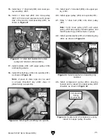
To use the edge sander, you must first configure
the machine for edge-sanding by removing the
spindle sanding components (if already installed)
and then installing the edge-sanding attachment.
1. DISCONNECT MACHINE FROM POWER!
2. If spindle sanding components are installed,
remove them (refer to
Spindle Sanding on
Page 18).
3. Install edge-sanding attachment in sander
body, as shown in
Figure 19.
4. Secure edge-sanding attachment to spindle
with edge-sanding attachment knob (see
Figure 19).
5. Install backstop and secure with wing bolt
(see
Figure 19).
Installing Edge-Sanding Attachment
Figure 19. Edge-sanding attachment installed.
Backstop
Edge-Sanding
Attachment
Wing Bolt
Knob
Содержание T27417
Страница 44: ......


