Grizzly H3390 Скачать руководство пользователя страница 3

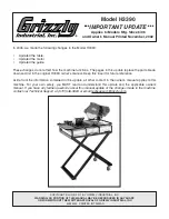
h3390 update (Mfg. since 6/06)

-3-

REF

PART #

DESCRIPTION

REF

PART #

DESCRIPTION

15

PW04M

FLAT WASHER 10MM

61

PH3390061

STAND BRACKET

16

PB13M

HEX BOLT M10-1.5 X 80

62

PTLW05M

EXT TOOTH WASHER 6MM

17

PH3390017

MOTOR PULLEY

63

PH3390063

KNOB M6-1.0

18

PSS30M

SET SCREW M10-1.5 X 10

64

PLN04M

LOCK NUT M8-1.25

19V2

PH3390019V2

MOTOR V2.06.06

65

PB47M

HEX BOLT M6-1 X 40

19V2-1 PH3390019V2-1 MOTOR FAN COVER V2.06.06

66

PH3390066

CASTER

19V2-2 PH3390019V2-2 TOGGLE SWITCH V2.06.06

67

PW03M

FLAT WASHER 6MM

19V2-3 PH3390019V2-3 RUBBER COVER V2.06.06

68

PN01M

HEX NUT M6-1

19V2-4 PH3390019V2-4 MOTOR FAN V2.06.06

69

PB22M

HEX BOLT M8-1.25 X 50

20V2

PH3390020V2

BLADE GUARD V2.06.06

70

PCB13M

CARRIAGE BOLT M6-1 X 20

22V2

PH3390022V2

Y-CONNECTOR V2.06.06

71

PH3390071

RUBBER WASHER

22-1

PH3390022-1

TUBING

80

PH3390080

END CAP

23

PH3390023

LOCK KNOB M8-1.25 X 30

81

PH3390081

LEFT REAR SPACER

24

PW01M

FLAT WASHER 8MM

82

PH3390082

BEARING MOUNT

25

PH3390025

BRAKE HOLDER

83

P608A

BALL BEARING 608

26

PH3390026

BRAKE SHAFT

84

PH3390084

LEFT ROLLER WHEEL

27

PEC13M

E-CLIP 5MM

85

PCAP128M

CAP SCREW M8-1.25 X 70

28

PH3390028

SPRING 1 X 35

86

PCAP02M

CAP SCREW M6-1 X 20

29

PN05M

HEX NUT M16-1.5

87

PLW03M

LOCK WASHER 6MM

30

PH3390030

OUTER FLANGE

88

PW03M

FLAT WASHER 6MM

32

PH3390032

INNER FLANGE

89

PH3390089

BEARING RETAINER M8-1.25

33

PH3390033

RUBBER BLOCK

90

PCAP33M

CAP SCREW M5-.8 X 12

34

PH3390034

MACHINE BED

91

PLW01M

LOCK WASHER 5MM

35

PCB14M

CARRIAGE BOLT M10-1.5 X 30

92

PW02M

FLAT WASHER 5MM

36

PH3390036

WHEEL COVER

93

PH3390093

LOCK PLATE

37

PCAP14M

CAP SCREW M8-1.25 X 20

94

PH3390094

RIGHT ROLLER WHEEL

38

PH3390038

V-BELT A-680

95

PRP56M

ROLL PIN 4 X 25

39

PCAP14M

CAP SCREW M8-1.25 X 20

96

PH3390096

RIGHT SPACER

40

PH3390040

PULLEY COVER

97

PCAP35M

CAP SCREW M8-1.25 X 60

41

PH3390041

DRIVE PULLEY

98

PSS26M

SET SCREW M5-.8 X 6

42

PK12M

KEY 5 X 5 X 30

99

PH3390099

SEAL

43

P6203ZZ

BALL BEARING 6203ZZ

100

PN03M

HEX NUT M8-1.25

44

PH3390044

SPINDLE

101

PH3390101

CHAIN

46V2

PH3390046V2

RAIL V2.06.06

102

PS38M

PHLP HD SCR M4-.7 X 10

49

PB09M

HEX BOLT M8-1.25 X 20

103

PH3390103

CORD CLIP

50

PLW04M

LOCK WASHER 8MM

104

PH3390104

LEFT BEARING SHIELD

52V2

PH3390052V2

WORK TABLE V2.06.06

105

PH3390105

CAP SCREW M8-1.25 X 6

53

PN03M

HEX NUT M8-1.25

106

PH3390106

RIGHT BEARING SHIELD

55

PW01M

FLAT WASHER 8MM

107

PH3390107

LEFT FRONT SPACER

56

PB126M

HEX BOLT M8-1.25 X 40

108

PN02M

HEX NUT M10-1.5

57

PH3390057

RIP FENCE

109

PW04M

FLAT WASHER 10MM

58

PH3390058

MITER FENCE 45D

110

PH3390110

WATER JET

59

PH3390059

PUMP

111

PH3390111

BAFFLE

59-1

PH3390059-1

CLEAR COOLANT HOSE

112

PS38M

PHLP HD SCR M4-.7 X 10

60

PH3390060

STAND BRACKET

Содержание H3390

Страница 1: ...ce the parts break down and list in the original H3390 owner s manual Keep this insert for future reference Aside from the information contained in this update all other content in the owner s manual...

Страница 2: ...07 108 109 109 109 109 100 Parts REF PART DESCRIPTION REF PART DESCRIPTION 1 PH3390001 WATER RESERVOIR 8 PLW06M LOCK WASHER 10MM 2 PH3390002 PLASTIC BLOCK 9 PW04M FLAT WASHER 10MM 3V2 PH3390003V2 HEX...

Страница 3: ...OUTER FLANGE 88 PW03M FLAT WASHER 6MM 32 PH3390032 INNER FLANGE 89 PH3390089 BEARING RETAINER M8 1 25 33 PH3390033 RUBBER BLOCK 90 PCAP33M CAP SCREW M5 8 X 12 34 PH3390034 MACHINE BED 91 PLW01M LOCK W...

Страница 4: ...TED IN CHINA ONLINE MANUAL DISCLAIMER THE INFORMATION IN THIS MANUAL REPRESENTS THE CONFIGURATION OF THE MACHINE AS IT IS CURRENTLY BEING SHIPPED THE MACHINE CONFIGURATION CAN CHANGE AS PRODUCT IMPROV...

Страница 5: ...als are Lead from lead based paints Crystalline silica from bricks cement and other masonry products Arsenic and chromium from chemically treated lumber Your risk from these exposures varies depending...

Страница 6: ...110V 6 GROUNDING 7 EXTENSION CORDS 7 4 SET UP 8 CLEAN UP 8 SITE CONSIDERATIONS 8 MAIN FEATURES 9 ASSEMBLY 10 13 BLADE CHANGES 13 START UP 14 LUBRICATION 15 5 OPERATION 16 CUT PREPARATION 16 CUTTING 1...

Страница 7: ...ymbols is described below Remember that safety messages by themselves do not eliminate danger and are not a substitute for proper accident prevention measures NOTICE Safety Instructions For Power Tool...

Страница 8: ...For Power Tools 14 MAINTAIN TOOLS WITH CARE Keep tools sharp and clean for best and safest performance Follow instructions for lubri cating and changing accessories 15 DISCONNECT TOOLS before servici...

Страница 9: ...ays wear a dust mask when cutting tile 10 Diamond Blades Diamond blades DO NOT cut material rather they grind materi Safety Instructions For Tile Saws al DO NOT feed the tile into the blade faster tha...

Страница 10: ...written to guide you through assembly review safety considerations and cover general operating procedures If you have any comments regarding this manual please write to us at the address below Grizzl...

Страница 11: ...y a fire could result Make sure your wiring recep tacle plug and circuit breaker can handle the amperage draw of the machine If you are not sure that your electrical circuit can handle the amperage dr...

Страница 12: ...this machine when it is not properly grounded can result in electric shock or electro cution No single list of electrical guidelines can be comprehensive for all shop environ ments Operating this mach...

Страница 13: ...ack of ventilation while using solvents could cause serious personal health risks fire or environmental hazards Always work in a well ventilated areas to pre vent the accumulation of dangerous fumes S...

Страница 14: ...wer Switch H Water Pump Plug In I V Belt Cover J Rip Fence K Table L 45 Bevel Miter Fence M Saw Blade N Circuit Reset Button O Blade Height Adjustment Knob Set up and operation instructions will be ea...

Страница 15: ...r they are formed Please examine the edges of all metal parts before handling them Failure to do so could result in injury Figure 4 Assembling the stand brackets Figure 5 Attaching the casters The ass...

Страница 16: ...Figure 8 Be sure the notched end of the pivot shaft is positioned correctly 6 Secure the assembly with a M10 1 5 x 10 setscrew as shown in Figure 8 7 Slide the pivot shaft into the mounting holes on t...

Страница 17: ...e runs from the pump to a Y connec tor and then slides through two mounting holes on each side of the blade guard base Figure 12 11 Slide the chrome table rail through the mounting holes on the table...

Страница 18: ...e 11 Page 12 3 Lift the blade guard to the up position and tighten the lock knob The blade guard should remain in the up position 4 Press the arbor lock pin Figure 17 and rotate the arbor nut by hand...

Страница 19: ...re the cord is positioned with a drip loop below the level of the outlet as shown in Figure 18 This prevents water from running down the cord and into the outlet Instead the water will drip to the flo...

Страница 20: ...em 1 Assemble the pump and hoses as described on Page 12 2 Position the pump so it does not interfere with the movement of the table 3 Fill the water reservoir with enough water to completely cover th...

Страница 21: ...Figure 20 3 Line up the saw blade with the cut line on the tile 4 Turn the saw on and allow to run for one minute Be sure the blade runs smoothly A constant stream of water should be flowing onto eac...

Страница 22: ...on the table does not produce accu rate cuts the scale and table position can be fine tuned by loosening the cap screws See Figure 21 and adjusting the table Figure 21 Table fine tuning cap screw Figu...

Страница 23: ...h 4 Worn or damaged cords and plugs 5 Damaged V belt 6 Any other condition that could hamper the safe operation of this machine 7 Inspect blades for damage 8 Guard alignment and operation Disconnect p...

Страница 24: ...Grizzly reminds you that each workshop is different and safety rules should be considered as they apply to your specific situation We recommend you keep a copy of our current catalog for complete info...

Страница 25: ...Sealed Permanently Lubricated Ball Bearings Cutting Capacity Maximum Blade Diameter 10 Maximum Depth of Cut at 90 33 4 Rip Cut Capacity 18 Diagonal Cut Capacity 12 Motor Type TEFC Capacitor Start Ind...

Страница 26: ...Wet Tile Saw 21 48 6 5 4 3 2 1 51 10 8 7 12 9 36 16 11 9 17 37 13 14 15 33 18 19 22 55 54 53 47 44 46 52 45 28 31 32 30 29 26 27 25 56 39 40 38 43 41 42 18 45 48 49 50 24 57 23 58 23 34 35 20 21 23 2...

Страница 27: ...22 H3390 Wet Tile Saw 61 70 65 66 68 67 64 63 62 60 69...

Страница 28: ...0 69 PB22M HEX BOLT M8 1 25 x 50 70 PCB08M CARRIAGE BOLT M6 1 0 X 20 1 PH3390001 WATER RESERVOIR 2 PH3390002 PLASTIC BLOCK 3 PB36M HEX BOLT M14 2 0 X 35 4 PW10M FLAT WASHER M14 5 PTLW04M TEETH WASHER...

Страница 29: ...24 H3390 Wet Tile Saw NOTES...

Страница 30: ...H3390 Wet Tile Saw 25 NOTES...

Страница 31: ...tried in the State of Washington County of Whatcom We shall in no event be liable for death injuries to persons or property or for incidental contingent spe cial or consequential damages arising from...

Страница 32: ...Which of the following magazines do you subscribe to ___American Woodworker ___Practical Homeowner ___Cabinetmaker ___Shop Notes ___Family Handyman ___Today s Homeowner ___Fine Homebuilding ___WOOD __...

Страница 33: ...ED LINE GRIZZLY INDUSTRIAL INC P O BOX 2069 BELLINGHAM WA 98227 2069 TAPE ALONG EDGES PLEASE DO NOT STAPLE Name_______________________________ Street_______________________________ City______________S...

Страница 34: ......

Страница 35: ...ly Trusted Proven and a Great Value OR SECURE ORDERING ORDERS SHIPPED WITHIN 24 HOURS E MAIL RESPONSE WITHIN ONE HOUR Visit Our Website Today And Discover Why Grizzly Is The Industry Leader Call Today...

Отзывы: