background image

-2-

G8748 Hand Tapping Machine

Assembly

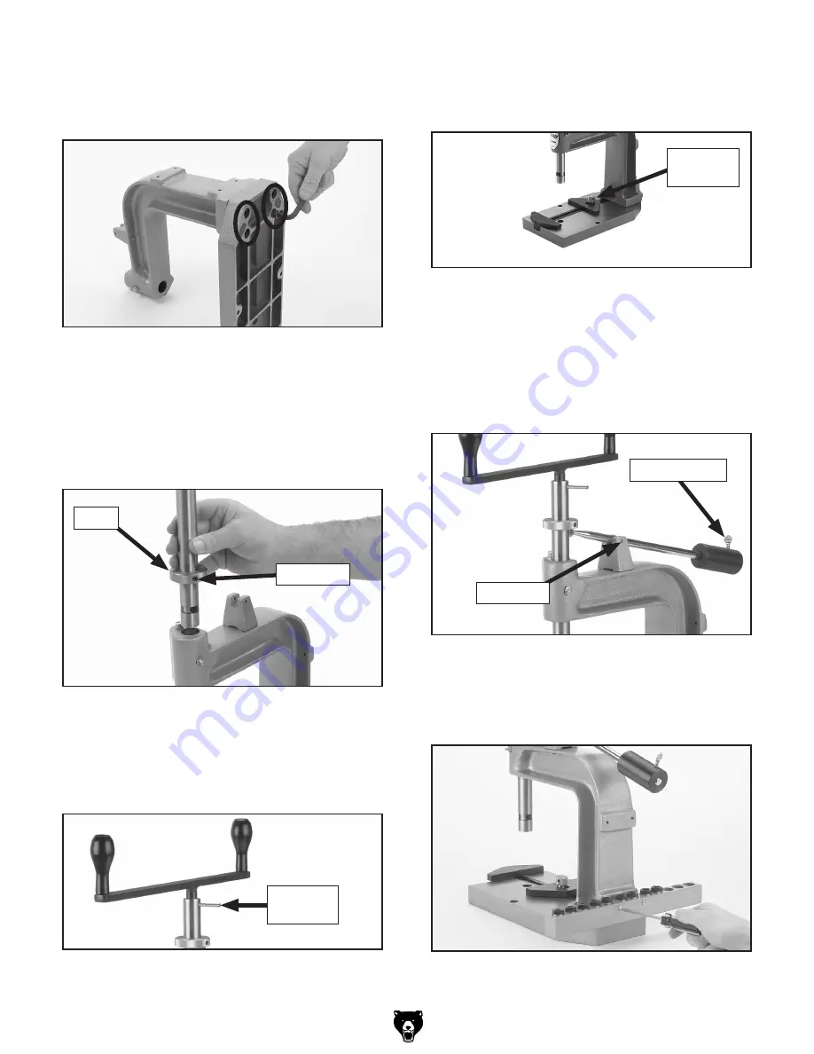
1.  Attach the L-frame to the base with four M10-

1.5 x 35 cap screws, as shown in 

Figure 3.

Figure 8. Attaching adapter rack to L-frame.

2.  Slide  the  collar  about  halfway  down  the 

spindle,  then  tighten  the  collar  set  screw  so 
the collar is secured to the spindle.

3.  Slide the spindle into the L-frame as shown in 

Figure 4.

Figure 4. Sliding spindle into L-frame.

Collar

Set Screw

4.  Insert the handle assembly into the top of the 

spindle,  then  slide  the  tapered  pin  through 
the  spindle  and  into  the  handle  assembly 
(

Figure 5).

6.  Attach the lever to the lever bracket with the 

dowel pin, then slide the counterbalance onto 
the  end  of  the  lever  and  secure  it  with  the 
thumbscrew (see 

Figure 7). The counterbal-

ance helps the spindle return to the up posi-
tion out of the way of the workpiece.

Figure 5. Handle assembly installed on spindle.

Tapered 

Pin

7.  Attach  the  adapter  rack  to  the  L-frame  with 

the two M5-.8 x 40 Phillips head screws, as 
shown in 

Figure 8.

Figure 7. Lever and counterbalance installed.

Dowel Pin

Thumb Screw

5.  Slide the fixed jaw into the slot on the base 

and secure the movable jaw with the knurled 
knob, as shown in 

Figure 6.

Figure 6. Vise jaws installed on base.

Knurled 

Knob

Figure 3. Attaching L-frame to base.

Содержание G8748

Страница 1: ...n 4 x 30mm 1 Taper Pin 1 Cleaning Remove shipping grease from all coated parts with a mild solvent or degreaser then re coat them with a light layer of oil to prevent rust MODEL G8748 HAND TAPPING MACHINE INSTRUCTIONS Figure 1 Model G8748 Hand Tapping Machine If you need help with your new item call our Tech Support at 570 546 9663 COPYRIGHT APRIL 2007 BY GRIZZLY INDUSTRIAL INC WARNING NO PORTION ...

Страница 2: ... the handle assembly Figure 5 6 Attach the lever to the lever bracket with the dowel pin then slide the counterbalance onto the end of the lever and secure it with the thumbscrew see Figure 7 The counterbal ance helps the spindle return to the up posi tion out of the way of the workpiece Figure 5 Handle assembly installed on spindle Tapered Pin 7 Attach the adapter rack to the L frame with the two...

Страница 3: ... workpiece with the vise To remove an adapter 1 Rotate the clip near the bottom end of the spindle until the detent ball is exposed 2 Pull the adapter out 3 Rotate the clip back over the detent ball to prepare the spindle for accepting another adapter Always wear safety glasses when tapping To prevent breaking taps follow these tips Drill a hole to the proper size for your tap refer to the documen...

Страница 4: ...6 GREASE FITTING 24 P8748024 COUNTERBALANCE 7 PB95M HEX BOLT M5 8 X 16 25 P8748025 THUMB SCREW 8 P8748008 L FRAME 26 P8748026 ADAPTER RACK 9 PN06M HEX NUT M5 8 27 P8748027 6 ADAPTER 10 PB93M HEX BOLT M5 8 X 30 28 P8748028 8 ADAPTER 11 P8748011 LEVER BRACKET 29 P8748029 10 ADAPTER 12 P8748012 DOWEL PIN 4 X 30MM 30 P8748030 1 4 ADAPTER 13 PSS07M SET SCREW M5 8 X 5 31 P8748031 5 16 ADAPTER 14 P874801...

Отзывы: