Model G4003 (Mfd. Since 6/20)
-27-
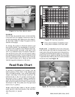
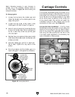
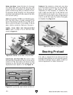
Figure 27. Spindle rotation control lever.
Spindle rotation control - The spindle rotation is
controlled from the lever on the right hand side
of the carriage. Moving the lever down causes
the spindle to rotate counter clockwise. Moving
the lever up causes the spindle to turn clockwise.
The middle position stops the motor and the lever
is considered to be in a neutral position. See
Figure 27.
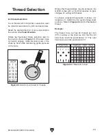
Cross Slide Handwheel - The Cross Slide
Handwheel moves the top slide toward and away
from the work. Turning the dial clockwise moves
the slide toward the workpiece. The graduated
dial can be adjusted by holding the handwheel
with one hand and turning the dial with the other.
Carriage Handwheel - The Longitudinal
Handwheel moves the carriage left or right along
the bed. The control is helpful when setting up the
machine for turning or when manual movement is
desired during turning operations.
Tool Post & Holder
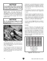
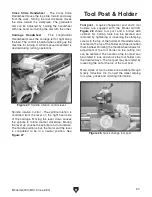
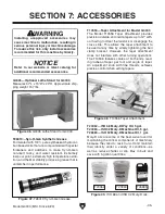
Figure 28. Quick change tool post.
Tool post - A quick change tool post and 2 tool
holders are supplied with the Model G4003.
Figure 28 shows tool post and a holder with
optional bit. Cutting tools can be secured and
removed by tightening or loosening the clamping
screws in the top of the holder. A threaded stud is
mounted in the top of the holder and has a knurled
thumb wheel. Rotating the thumb wheel allows for
adjustment of the tool holder so the cutting tool
can be centered. The handle on the tool post can
be rotated to lock and unlock the tool holder onto
the dovetail ways. The tool post may be rotated by
loosening the nut at the top of the tool post.
More styles of tool holders are available through
Grizzly Industrial, Inc. Consult the latest catalog
for styles, prices and ordering information.

