Grizzly G1022PRO Скачать руководство пользователя страница 38

-36-

G1022 Series Contractor Saws

4.

If anything appears abnormal, immediately
turn off the saw and fix the problem. If a
problem exists that is beyond the scope of
this manual, call our service department.

5.

If the saw is behaving normally, turn it off and
prepare to make a cut according to the
instructions outlined in the following sec-
tions.

Blade Selection

Choosing the correct blade for the job is essential
for the safe and efficient use of your table saw.
Ignoring this important step could result in dam-
age to the saw and serious injury to the operator.
Documented below are the most common saw
blades and their uses. 

1.

Rip Blade:

Used for cutting with the grain.

Typically, 10" rip blades have between 20-40
teeth (

Figure 50

), flat-top ground tooth pro-

file and large gullets to allow for large chip
removal.

Figure 50. 

Ripping blade.

3.

Combination Blade:

Used for cutting with

and across the grain. A compromise
between a rip blade and a cross-cut blade, a
10" combination blade will typically have
between 40-50 teeth (

Figure 52

), an alter-

nate top bevel and flat or alternate top bevel
and raker tooth profile. The teeth are
arranged in groups of five. The gullets are
small and shallow within the groups of five
teeth, similar to a cross-cut blade; then large
and deep between the groups, like a ripping
blade. 

Figure 52. 

Combination blade.

2.

Cross-cut Blade:

Used for cutting across

the grain. 10" cross-cut blades have
between 60-80 teeth (

Figure 51

), alternate

top bevel or steep alternate top bevel tooth
profiles, small hook angle and a shallow gul-
let.

Figure 51. 

Crosscutting blade.

Содержание G1022PRO

Страница 1: ...PRO INSTRUCTION MANUAL COPYRIGHT MARCH 2002 BY GRIZZLY INDUSTRIAL INC WARNING NO PORTION OF THIS MANUAL MAY BE REPRODUCED IN ANY SHAPE OR FORM WITHOUT THE WRITTEN APPROVAL OF GRIZZLY INDUSTRIAL INC PR...

Страница 2: ...ls are Lead from lead based paints Crystalline silica from bricks cement and other masonry products Arsenic and chromium from chemically treated lumber Your risk from these exposures varies depending...

Страница 3: ...E 23 BLADE 23 BLADE GUARD 24 25 TABLE INSERT 26 5 ADJUSTMENTS G1022SM FENCE 27 29 G1022Z FENCE 29 30 BLADE PARALLELISM 31 32 45 90 POSITIVE STOPS 33 WORM GEAR 34 MITER GAUGE 34 6 OPERATIONS PRE RUN CH...

Страница 4: ...lam mable or noxious fumes may exist Keep work area well lighted For Your Own Safety Read Instruction Manual Before Operating This Equipment Indicates an imminently hazardous situation which if not av...

Страница 5: ...16 14 11 12 16 16 14 13 16 14 12 12 17 20 12 12 10 21 30 10 10 No Safety Instructions For Power Tools 16 REDUCE THE RISK OF UNINTENTION AL STARTING On machines with mag netic contact starting switche...

Страница 6: ...E the rip fence out of the way when crosscutting 9 NEVER use the miter gauge and rip fence at the same time 10 NEVER attempt to free a stalled saw blade without first turning the saw OFF 11 PROVIDE ad...

Страница 7: ...in the Grizzly catalog Be sure to hold the insert firmly in place with a piece of wood when creating slots Never hold the table insert with your hand while cutting new slots Safety Accessories Statis...

Страница 8: ...Easily made from scrap stock featherboards provide an added degree of protection against kickback as shown in Figure 4 To make a featherboard cut a 30 40 angle at one end of the board and make a numb...

Страница 9: ...ives for profile cutting We DO NOT recom mend the use of a moulding head as they require advanced skills in their operation Parallel Being an equal distance apart at every point i e the rip fence face...

Страница 10: ...or a 20 amp slow blow fuse The circuit you use should be dedicated i e the machine should provide the only draw from that circuit If frequent circuit failures occur when using this machine contact ou...

Страница 11: ...t switch near the machine Check the electrical codes in your area for specifics on wiring requirements Under normal use the motor draws approximate ly 13 amps at 220V We recommend a 15 amp cir cuit br...

Страница 12: ...g with your local municipality or a licensed electrician Grounding Extension Cords In the event of an electrical short grounding pro vides electric current a path of least resistance to reduce the ris...

Страница 13: ...tfeed rollers and a mobile base Please refer to our cur rent catalog for prices and ordering information We are also pleased to provide this manual with the Model G1022 Series It was written to guide...

Страница 14: ...the Model G1022 Series as supplied when the manual was prepared However owing to Grizzly s policy of continuous improvement changes may be made at any time with no obligation on the part of Grizzly W...

Страница 15: ...Seek assistance before beginning assembly Some metal parts may have sharp edges on them after they are formed Please examine the edges of all metal parts before handling them Failure to do so could re...

Страница 16: ...Guard Hardware Bag Qty Description 4 Hex Bolt M8 1 25 x 25 8 Flat Washer M8 4 Hex Nut M8 1 25 Motor Mount Hardware Bag Qty Description 40 Carriage Bolt M8 1 25 x 16 4 Hex Bolt M8 1 25 x 19 48 Flat Was...

Страница 17: ...23 4 3 LINES ARE 1MM APART LINES ARE 1 16 INCH APART 5 8 W A S H ER DIAM E T E R 9 16 W A S H ER DIA M E T E R 1 2 W A S H ER DIA M E T E R 12mm W A S H ER DIAM E T E R 10mm W A S H ER DIA M E T E R...

Страница 18: ...t Most commercial or home shop floors should be sufficient to carry the weight of the Model G1022 Series If you question the strength of your floor you can opt to reinforce it WORKING CLEARANCES Worki...

Страница 19: ...up and out of the way of machinery and keep hair pulled back Wear safety glasses dur ing the entire assembly process Failure to com ply may result in serious personal injury Some metal parts may have...

Страница 20: ...Secure with M8 1 25 x 19 hex bolts 8MM flat washers and M8 1 25 hex nuts with the dust port sandwiched between as shown in Figure 11 4 Bolt the other side panel to the upper and lower braces using the...

Страница 21: ...2 Mounting the handwheels To mount the handwheels 1 Position a handwheel over the arbor raising shaft on the front of the saw Be sure it fits completely over the shaft The slots in the handwheel hole...

Страница 22: ...in the motor plate and insert the motor pivot rod making sure the groove in the rod lines up with the setscrew in the mount bracket as shown in Figure 16 Tighten the setscrew Figure 17 Attaching moto...

Страница 23: ...o sure Simply connect the quick disconnect on the cord between the switch and motor G1022ZF G1022ZFX and G1022PRO The ON OFF switch on the ZF ZFX and PRO models mounts directly below the front fence r...

Страница 24: ...of the machine with the markings facing up 2 Insert the round plastic plugs into the ends of each rail The Model G1022SM and Z are supplied with round rails the Model G1022ZF and ZFX are supplied with...

Страница 25: ...ge from the arbor Note that there is a 3 4 diameter spacer on the arbor shaft Remove and discard it Remember the arbor nut is a left handed thread 2 Install the saw blade onto the arbor Ensure that th...

Страница 26: ...mounting bolts to the mounting slots on the guard Figure 26 Blade guard components 4 Tighten the mounting bolts to secure the blade guard 5 Using a machinist s or a combination square align the face o...

Страница 27: ...t section otherwise continue with the next step 9 If the splitter is positioned to the left of the blade alignment cannot be achieved by washer placement Adjustment of the front support bracket is req...

Страница 28: ...will not come into contact with table insert Position the blade at 90 then raise and lower the blade through its full range of motion Also rotate the blade while doing this making sure that the blade...

Страница 29: ...tions on adjusting The fence must engage and square up on the front rail before the rear clamp engages the back rail In essence the rear clamp should act as a secondary mechanism for maintaining fence...

Страница 30: ...l 6 Loosen the locking lever and slide the fence along the rail Return the fence to its position at the edge of the miter slot and slowly apply pressure to the lever If adjustments are cor rect the fe...

Страница 31: ...should only begin to apply pressure on the back rail over the last one third of its stroke To adjust the fence 1 First make sure the front clamp is engaging the front rail with the lock handle at one...

Страница 32: ...d slide the fence along the rail Return the fence to its position at the edge of the miter slot and slowly apply pressure to the lever If adjustments are cor rect the fence should square itself before...

Страница 33: ...ence in measurements is less than 0 004 your blade and table are in acceptable align ment move to Step 7 If the difference is greater you will need to adjust the trunnion and table 4 To adjust blade...

Страница 34: ...re all the same thickness and you put an equal number under each of the two corners 11 Tighten down one trunnion bolt a small amount and then move on to each of the oth ers tightening each down the sa...

Страница 35: ...iation between the blade and square 5 If a gap exists at either the top or the bottom of the square loosen lock nut A and adjust ment bolt B indicated in Figure 47 Figure 46 Checking blade angle to ta...

Страница 36: ...t A B Miter Gauge Initial Step Model G1022ZF and ZFX The ZF ZFX miter gauge has two setscrews in the miter slot bar which can be set to remove any free play from the miter gauge when inserted in the T...

Страница 37: ...config ured 6 Have you checked your work piece for obvi ous defects 7 Are the V belts properly tensioned and the pulleys properly aligned 8 Is the guard assembly installed and func tional 9 Have you c...

Страница 38: ...lades have between 20 40 teeth Figure 50 flat top ground tooth pro file and large gullets to allow for large chip removal Figure 50 Ripping blade 3 Combination Blade Used for cutting with and across t...

Страница 39: ...and holds individual moulding knives We do not rec ommend their use They are very dangerous and required training beyond the scope of this manual This section on blade selection is by no means compre...

Страница 40: ...and fence and push the workpiece fully past the blade When a small width is to be ripped and a push stick can not be safely put between the blade and rip fence rip a larger piece to obtain the desired...

Страница 41: ...th of the dado Make sure the dado blade will not cut through the work piece 6 If dadoing along the length of your work piece adjust the distance between the fence and the inside edge of the blade to s...

Страница 42: ...6 Turn on the saw and make a second cut 7 Move toward the center of the dado with your subsequent cuts until the dado is complete 8 Re install the blade guard In addition to its ability to create a va...

Страница 43: ...must be removed from the saw ALWAYS replace the blade guard after dadoing is complete Instructions on using moulding heads have been intentionally left out They are very dangerous when not used prope...

Страница 44: ...and out of the way of machinery and keep hair pulled back Wear safety glasses dur ing the entire mainte nance process Failure to comply may result in serious personal injury V Belt Inspect regularly f...

Страница 45: ...G1022 Series Contractor Saws 43 G1022SM AND Z WIRING DIAGRAM...

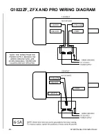
Страница 46: ...44 G1022 Series Contractor Saws G1022ZF ZFX AND PRO WIRING DIAGRAM...

Страница 47: ...ed in Section 3 Introduction Additional information sources are necessary to realize the full potential of this machine Trade journals woodworking magazines and your local library are good places to s...

Страница 48: ...um Blade Diameter 10 Maximum Depth of Cut at 90 31 8 Blade Tilt 0 45 Right Maximum Depth of Cut at 45 21 8 Maximum Rip to Right of Blade Standard 24 Maximum Rip to Right of Blade Optional Extension Ra...

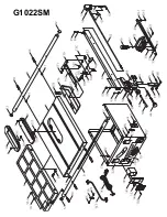
Страница 49: ...G1022SM...

Страница 50: ...G1022SM...

Страница 51: ...G1022SM...

Страница 52: ...2033 STOP LINK 35 PCB01M CARR BOLT M8 1 25x20 35 1 PN03M HEX NUT M8 1 25 35 2 PW01M FLAT WASHER 8MM 37 P1022037 WIDTH POINTER 38 P1022038 FENCE ADJUSTER 39 P1022Z039 FRONT CLAMP 40 P1022040 ECCENTRIC...

Страница 53: ...0 PB26M HEX BOLT M8 1 25 x 30 141 PB03M HEX BOLT M8 1 25 x 16 142 P1022142 CONNECTING PLATE 143 PN03M HEX NUT M8 1 25 144 PW01M FLAT WASHER 8MM 145 P1022145A SWITCH BRACKET 146 P1022146 SWITCH 147 PWR...

Страница 54: ...st Iron Open Ribbed Design Cutting Capacity Maximum Blade Diameter 10 Maximum Depth of Cut at 90 31 8 Blade Tilt 0 45 Right Maximum Depth of Cut at 45 21 8 Maximum Rip to Right of Blade Standard 24 Ma...

Страница 55: ...G1022Z...

Страница 56: ...G1022Z...

Страница 57: ...G1022Z...

Страница 58: ...L PIN 3 x 16 98 PN05M HEX NUT M16 1 5 99 P1022099 FRONT TRUNNION REF PART DESCRIPTION 1 P1022001 TABLE INSERT 1A P1022001 A DADO INSERT 2 PSS04M SETSCREW M6 1 0 x 12 3A P1022Z003A STAND LEG 3 1 P10220...

Страница 59: ...3 PN03M HEX NUT M8 1 25 144 PW01M FLAT WASHER 8MM 145 P1022145A SWITCH BRACKET 146 P1022146 SWITCH 147 PWRCRD110S POWER CORD 147 1 PWRCRD110L MOTOR CORD 148 P1022148 SPANNER WRENCH 149 P1022149 PULLEY...

Страница 60: ...Maximum Blade Diameter 10 Maximum Depth of Cut at 90 31 8 Maximum Depth of Cut at 45 21 8 Maximum Rip to Right of Blade Standard 25 Maximum Rip to Right of Blade Optional Extension Rails 48 Maximum Ri...

Страница 61: ...G1022ZF ZFX PRO...

Страница 62: ...G1022ZF ZFX PRO...

Страница 63: ...G1022ZF ZFX PRO...

Страница 64: ...TOR PLATE ROD 132 P1022132 MOTOR PLATE 133 PB07M HEX BOLT M8 1 25 x 25 134 PW01M FLAT WASHER 8MM REF PART DESCRIPTION 1 P1022ZF001 TABLE INSERT 1A P1022001 A DADO INSERT 2 PSS04M SETSCREW M6 1 0 x 12...

Страница 65: ...9 PULLEY GUARD BRACKET 150 PB10 HEX BOLT 1 4 20 x 2 152 P1022152 SLEEVE 153 P1022153 PULLEY COVER 154 PWN02 WING NUT 1 4 20 155 P1022Z155 UPPER BRACKET LONG 155 1 P1022Z155 1 UPPER BRACKET SHORT 155 2...

Страница 66: ...is incorrect Table top too low 1 Hand wheel key is inserted too far 2 Bullets are wedged 3 Roll pin or setscrew in worm gear is contacting geared trunnion CORRECTIVE ACTION 1 Check power line for pro...

Страница 67: ...PUSH STICK MAKE FROM 1 2 OR 3 4 WOOD OR THICKNESS LESS THAN WIDTH OF MAT L TO BE CUT CAUTION USE ONLY GOOD STRONG WOOD OR PLYWOOD 1 2 GRID CUT HERE TO PUSH 1 2 WOOD CUT HERE TO PUSH 1 4 WOOD NOTCH TO...

Страница 68: ...erican Woodworker ___Practical Homeowner ___Cabinetmaker ___Shop Notes ___Family Handyman ___Today s Homeowner ___Fine Homebuilding ___WOOD ___Fine Woodworking ___Wooden Boat ___Home Handyman ___Woods...

Страница 69: ...l be tried in the State of Washington County of Whatcom We shall in no event be liable for death injuries to persons or property or for incidental contingent spe cial or consequential damages arising...

Страница 70: ...GRIZZLY INDUSTRIAL INC P O BOX 2069 BELLINGHAM WA 98227 2069 TAPE ALONG EDGES PLEASE DO NOT STAPLE Name_______________________________ Street_______________________________ City______________State____...

Страница 71: ......

Страница 72: ......

Отзывы: