


Model g0716 (Mfg. since 2/11)
-43-
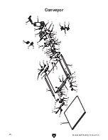
conveyor parts List
REF PART #
DESCRIPTION
REF PART #
DESCRIPTION
101
P0716101
CONVEYOR BELT
126
PS02M
PHLP HD SCR M4-.7 X 12
102
PCAP24M
CAP SCREW M5-.8 X 16
131
P0716131
SWITCH HOUSING BRACKET
103
P0716103
COMPRESSION SPRING
132
P0716132
TERMINAL BLOCK 4P
104
P0716104
INFEED ROLLER BRACKET
133
P0716133
SWITCH HOUSING PLATE
105
PN01M
HEX NUT M6-1
134
P0716134
TRANSFORMER OMRON HF-7A 24/120V
106
P0716106
ADJUSTABE SLIDE
135
PS38M
PHLP HD SCR M4-.7 X 10
107
PS115M
PHLP HD SCR M6-1 X 90
136
PB03M
HEX BOLT M8-1.25 X 16
108
P0716108
FEED ROLLER BUSHING
137
P0716137
INSULATION PLATE
109
P0716109
OUTFEED ROLLER
138
P0716138
STRAIN RELIEF 1/2" SNAP-IN
110
PW02M
FLAT WASHER 5MM
139
P0716139
POWER CORD 14G 3C 10' 5-15
111
PLW01M
LOCK WASHER 5MM
140
P0716140
CONVEYOR MOTOR 24VDC
112
PN06M
HEX NUT M5-.8
141
P0716141
SWITCH HOUSING
113
PW01M
FLAT WASHER 8MM
142
P0716142
INSULATION PAD
114
PCAP58M
CAP SCREW M8-1.25 X 12
143
PB08M
HEX BOLT M6-1 X 20
115
P0716115
ADJUSTABLE SLIDE BRACKET
144
P0716144
CONVEYOR CLUTCH
116
PCB22M
CARRIAGE BOLT M6-1 X 16
145
PW05M
FLAT WASHER 4MM
117
PW03M
FLAT WASHER 6MM
146
PW02M
FLAT WASHER 5MM
118
PLW03M
LOCK WASHER 6MM
147
P0716147
VS FEED DIAL HF-7A 071015
119
P0716119
INFEED ROLLER
148
PS19M
PHLP HD SCR M5-.8 X 6
120
PS06M
PHLP HD SCR M5-.8 X 20
149
PN04M
HEX NUT M4-.7
124
P0716124
SWITCH COVER
150
PS09M
PHLP HD SCR M5-.8 X 10
125
G8988
GRIZZLY SAFETY ON/OFF SWITCH
151
P0716151
CONVEYOR PLATEN


