background image

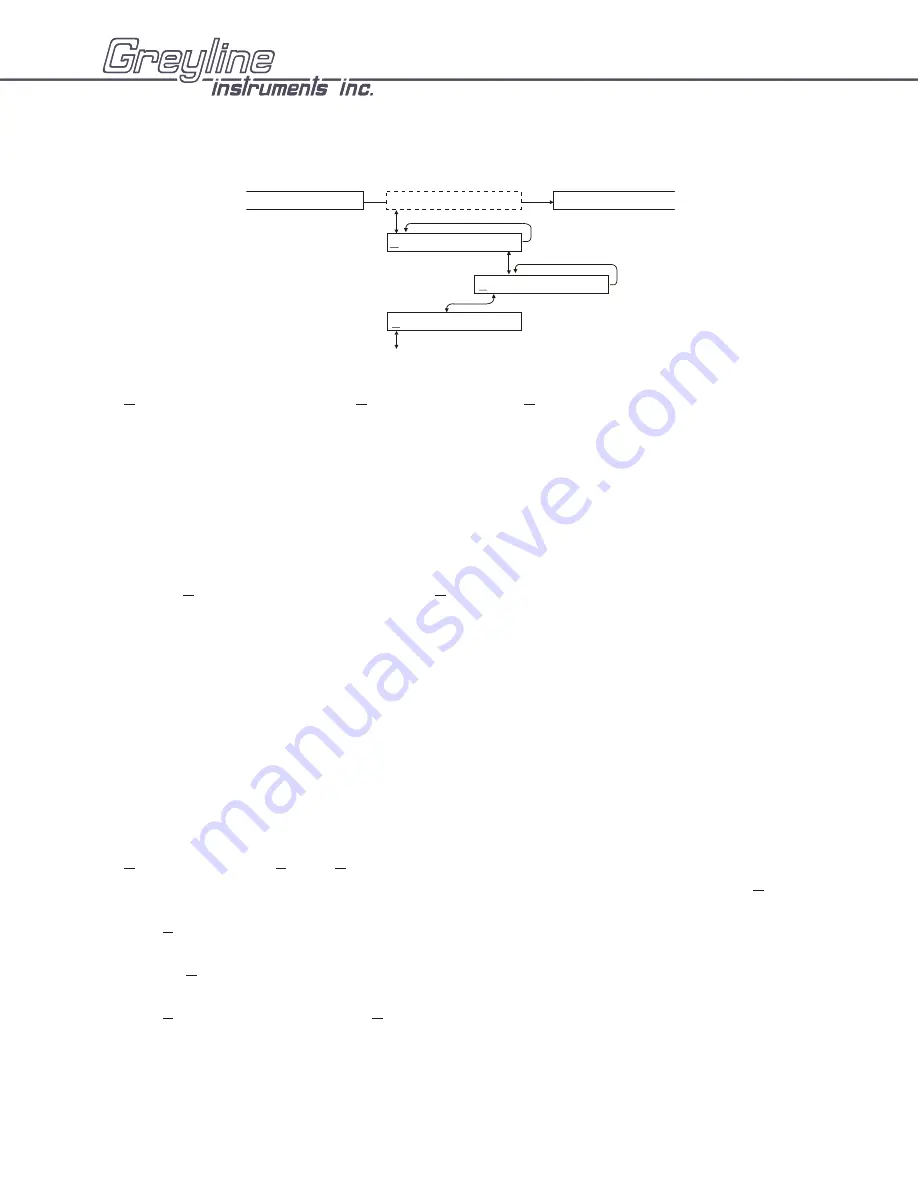
DATA LOGGING (Optional)
Setup

From 

RUN STOP SETUP 

 press 

Æ

 to 

SETUP

 and then 

È

  to 

Log Site ID  0

.


Press 

Æ

 to position the

cursor under the numeral and 

È

 or 

Ç

  to change the numerals. The “Site ID” number is retained with

data logging sessions to identify logs stored from different locations. 

Regardless of the logging mode selected a 24 hour flow report will be created and displayed under the

24 HR LOG

 menu

Formatted Data

Press 

È

 from 

Log Site ID


and press 

È

 from  

Formtd

.

Formtd

” data stores a summary of flow readings over a user-selectable time period. The summary

includes:

DATE and TIME
Interval TOTAL
Interval AVERAGE
Interval MAX FLOW
Interval MAX FLOW TIME
Interval MIN FLOW
Interval MIN FLOW TIME

From 

Formtd 

press 

È

 to 

Start MMM DD/YYYY 

(eg: 

Jan 01/2000

). Press 

Æ

 to position the cursor

and then 

È

 or 

Ç

 to set the Month, Day and Year that logging will Start. Press 

Æ

 to return to 

Start

.

Press 

È

 to 

Start

 (time) and 

Æ

 to position the cursor under the time column 

HH/MM/SS

 (24 hour

clock in Hours/minutes/seconds, eg: 

23:02:16

) and then 

È

 or 

Ç

 to set the logging start Time. Press 

Æ

 to return to 

Start

 .

Press 

È

 to 

Interval

 and 

Æ

 to the 

Hrs

 column. Press 

È

 or 

Ç

  to select the flow logging interval.

Choose from: 

24 Hrs

, or  

12 Hrs

, or  

8 Hrs

, or  

4 Hrs

, or  

1 Hrs

AVFM-II Area-Velocity Flow Meter

Manual Series A.10

Page 35

   DATA  LOGGING

Log  Site ID      1

RUN   STOP   Setup

PASSWORD: 00

UNITS / MODE

Formtd Trend  LVT

Содержание AVFM-II

Страница 1: ...USER S GUIDE Installation Operation Instructions Area Velocity Flow Meter Model AVFM II Manual Series A 10 ...

Страница 2: ...Note This page has been left blank intentionally ...

Страница 3: ...low Meter Manual Series A 10 INDEX Function Test 4 Connections 4 Keypad System 4 Menu Flow Chart 5 Run 7 Totalizer 8 Password 8 Units Mode 9 Calibration for Open Channel Flow 12 Sensor Cleaning Instructions 24 Relay Parameters 14 Special Functions 15 Sensor Location 17 Enclosure Installation 21 Field Troubleshooting 23 Sensor Cleaning Instructions 24 Applications Hotline 25 Product Return Procedur...

Страница 4: ...ng B Select Velocity mode and stir the water to see a velocity reading CONNECTIONS POWER INPUT The standard model requires AC power input between 100 130VAC 50 60Hz 2 amp fuse is recommended No adjustments are necessary for any voltage in this range Optional 230VAC requires power input between 200 260VAC 50 60Hz See OPTIONS section of this manual for connection of optional 9 36VDC power input IMPO...

Страница 5: ...ENU FLOW CHART The following diagram shows part of the AVFM II Menu system Arrows show the three directions to leave a box Pressing a corresponding keypad arrow will move to the next box in the direction shown Move the cursor or underline under numerals to increase or decrease the number with the È Ç keys At the bottom of each Menu column is a Store Yes box To store the calibration values permanen...

Страница 6: ...re Yes CHANNEL SETUP Round Width Width UNITS MODE ft in m cm Range Store Yes ft3 USG USMG IG IMG m3 L s min hr d Chan ID Square Level Flow Velocity Trapezd Slope Egg Height MaxV 10 00 ft s MaxF 10 000 ft3 s MinRg 1 333 ft MaxRg 32 00 ft Damping 20 Store Yes MaxLvl 3 000 ft MinLvl 0 125 ft Relays 1 2 Tot SCv EC 8 SPECIAL FUNCTION AVFMII V 2 86 RELAY PARAMETERS Pulse R1 Function Off R1on 0 00 ft3 Fl...

Страница 7: ...fluid measured by the instrument ECHO CONFIDENCE Level From RUN use ÈÈÈ to view Echo Confidence EC This indicator displays the echo strength for the level measurement SIGNAL CONFIDENCE Velocity From Run use ÈÈÈÈ to view Signal Confidence SC This indicates consistent or widely varying flow rates and helps gauge the quality of the velocity signal in the application AVFM II Area Velocity Flow Meter M...

Страница 8: ...ized relays will be displayed in reverse type RELAYS PASSWORD The password a number from 00 to 99 prevents unauthorized access to the CALIBRATION menu From RUN scrolling display press Æ to PASSWORD Press Æ to place the cursor under the digits and È or Ç to change the number and then Æ to proceed to CALIBRATION Factory default Password is 00 A new password can be stored by going Æ to SPECIAL FUNCTI...

Страница 9: ... Press È to make your selection ft3 cubic feet USG US gallons USMG US million gallons FLOW only IG Imperial gallons IMG Imperial million gallons FLOW only m3 cubic meters L liters Press Æ to position the cursor underneath your selection and press È to make your selection Repeat for selection of time units s seconds min minutes hr hours d day Note The AVFM II will display Er ILLEGAL UNITS if your c...

Страница 10: ...nge the numbers and decimal point Egg Select Egg for channels with cross section dimensioned as shown Press È to Height and Æ to edit the channel height Press Ç and È to change numbers and decimal point Page 10 Manual Series A 10 AVFM II Area Velocity Flow Meter R 3R R 2 2R HEIGHT 3R CALIBRATION Store Yes CHANNEL SETUP Round Width Width UNITS MODE Chan ID Square Trapezd Slope Egg Height ...

Страница 11: ...ls Press È to Width and Æ to edit the channel width Use È and Ç to change the numbers and decimal point When channel type and all units have been selected press È to Store and then Æ to Yes and È or Ç to CALIBRATION Page 11 AVFM II Area Velocity Flow Meter Manual Series A 10 SLOPE RISE RUN e g 1 WIDTH RUN RISE 24 10 12 e g 2 WIDTH RUN RISE 1 m 0 35 m 0 5 m SLOPE RISE RUN 1 2 SLOPE RISE RUN 1 429 T...

Страница 12: ...mum velocity measured in LVT logging mode Press È to LvlOFFSET Set to 0 00 when sensor is mounted on the floor of the channel When sensor is mounted above the floor of the channel enter the distance between channel floor and bottom of sensor Manual Series A 10 AVFM II Area Velocity Flow Meter Page 12 RELAY PARAMETERS CHANNEL SETUP CALIBRATION MaxV 10 00 ft s MaxF 10 000 ft3 s MinRg 1 333 ft MaxRg ...

Страница 13: ...tance from the optional PZ12 LP sensor to the highest water level must be 8 203 mm Use È and Ç to enter the minimum range MaxRg is distance from the PZ12 LP sensor to the zero water level must be 12 3 66 m Press È to Damping Default setting is 2 to allow quick set up of the instrument 20 should be ideal for most applications Increased damping up to 99 slows the AVFM II s response to turbulence and...

Страница 14: ...he relay R1Off use È and Ç to set the Off flow velocity Selection of Level mode will disable this function Level Press È to select level mode for the relay then R1on Use È and Ç to set the On level to energize the relay R1Off Use È and Ç to set the Off level R1 LOE Press Æ to select Off Æ On Æ Hold In a loss of echo condition the relay will turn off de energize on energize or hold its current stat...

Страница 15: ...PECIAL FUNCTION AVFMII V 2 86 Tag 01 Date May 31 1999 Time 23 39 51 View Codes Yes 1234567890123456 LOE Time 30 s Reset Tot Yes Temp 20 3 C º Min Temp 20 0 C º Max Temp 23 0 C º DISPLAY C F º º Cal Const 1 000 ISB No Yes Defaults Yes Simul 0 00 New Password 00 Com 96 192 Store Yes ...

Страница 16: ...isplay the minimum and maximum temperatures the AVFM II has sensed Press Æ to Display C F Position the cursor under C for celcius display or F for Farenheight display Press È to return to Temp ISB No Yes Select Yes only when the instrument is equipped with an optional Intrinsic Safety Barrier for sensor mounting in hazardous locations This setting compensates for the electrical characteristics of ...

Страница 17: ...mum Head level and 10 times the channel width from these flow disturbances QZ02L VELOCITY LEVEL SENSOR MOUNTING Mount the QZ02L sensor with the stainless steel bracket and hardware supplied Ensure that the sensor is parallel to the water surface check with a level Mount with the tapered end of the sensor pointing upstream and the sensor cable pointing downstream Clip or tie wrap the sensor cable s...

Страница 18: ...Page 18 Manual Series A 10 AVFM II Area Velocity Flow Meter GOOD BAD SENSOR END VIEW SENSOR END VIEW SENSOR END VIEW SENSOR END VIEW SENSOR SENSOR SENSOR FLOW SENSOR FLOW ...

Страница 19: ...friction fit Insert the sensor into the mounting bracket and clip or tie wrap the sensor cable securely to the stainless steel pipe band as illustrated OPTIONAL QZ02L DP VELOCITY SENSOR MOUNTING Mount the velocity sensor at the bottom of the channel or pipe in a position where it will be continuously submerged The QZ02L DP velocity sensor does not have to be exactly parallel to the water surface P...

Страница 20: ...bove the high water level Install the stainless steel mounting bracket in a horizontal position check with a level and then insert the PZ12 LP sensor Page 20 Manual Series A 10 AVFM II Area Velocity Flow Meter WATER PZ12 LP PZ12 LP MANHOLE MOUNTING PZ12 LP WATER PZ12 LP PIPE MOUNTING QZ02L DP VELOCITY SENSOR PZ12 LP SENSOR MB12 MOUNTING BRACKET ...

Страница 21: ...cover 2 Insert 8 screws and washers through the four enclosure mounting holes to secure enclosure to wall or mounting stand 3 Close cover Additional conduit holes can be cut in the end of the enclosure when required Use a hole saw or Greenlee type hole cutter to cut the required holes Note This non metallic enclosure does not automatically provide grounding between conduit connections Grounding mu...

Страница 22: ...l to 8 20 3 cm Er ILLEGAL UNITS Your choice of UNITS exceeds a maximum value of 9 999 999 Use US MGD Imp MGD or m3 d so that UNITS will be 9 999 999 or less Err ILLEGAL SPAN The value entered for MaxRg is the same or less than MinRg 2 Maximum range must be greater than minimum range or on the large display Your choice of Units exceeds 9 999 999 Use USMG d IMG d or m3 d so that Units will be 9 999 ...

Страница 23: ...he SPECIAL FUNCTION menu will return the instrument to as shipped factory settings LEVEL QZ02L SENSOR SYMPTOMS FAULTS SOLUTIONS EC bar graph at zero very turbulent flow Increase LOE time SPECIAL FUNCTION very aerated flow relocate sensor or use PZ12 LP sensor not level level sensor with Bullseye level sediment dirt grease build up on sensor clean sensor Level display reads 1 0 inches Level less th...

Страница 24: ...ts water for 5 minutes Do not immerse open end of sensor cable or cable plug Ensure that the protective cap is properly fitted to the cable plug before immersing in water or cleaning solution 3 Remove grease from sensor with clean water and mild soap Do not use abrasive cleaners solvents or high pressure washers SENSOR CLEANING WHILE AVFM II IS IN OPERATION Use a soft brush or broom to wipe the se...

Страница 25: ...pplications Hotline below United States Tel 315 788 9500 Fax 315 764 0419 Canada Tel 613 938 8956 Fax 613 938 4857 Toll Free 888 473 9546 Email info greyline com Web Site http www greyline com Greyline Instruments Inc Canada USA 16456 Sixsmith Drive 105 Water Street Long Sault Ont K0C 1P0 Massena NY 13662 Page 25 AVFM II Area Velocity Flow Meter Manual Series A 10 ...

Страница 26: ... will not be serviced and will be returned to the sender at their expense 1 Rinse sensor and cable to remove debris 2 If the sensor has been exposed to sewage immerse both sensor and cable in a solution of 1 part household bleach Javex Clorox etc to 20 parts water for 5 minutes Important do not immerse open end of sensor cable 3 Dry with paper towels and pack sensor and cable in a sealed plastic b...

Страница 27: ...long with a copy of your invoice This warranty does not cover damages due to improper installation or handling acts of nature or unauthorized service Modifications to or tampering with any part shall void this warranty This warranty does not cover any equipment used in connection with the product or consequential damages due to a defect in the product All implied warranties are limited to the dura...

Страница 28: ...les in a metal conduit Extended sensor cable can be installed in conduit for mechanical protection Recommended installation with a metal junction box is illustrated below COAXIAL CABLE PREPARATION DXC Doppler sensor cable can be cut and spliced up to a maximum length of 500 ft 152 m Cable ends must be prepared as illustrated below Manual Series A 10 AVFM II Area Velocity Flow Meter Page 28 CONDUIT...

Страница 29: ... BOX OPTION VJB Optional Watertight steel NEMA4 IP55 Junction Boxes with terminal strips are available from Greyline Instruments AVFM II Area Velocity Flow Meter Manual Series A 10 Page 29 DIMENSIONS OPTION VJB JUNCTION BOX ...

Страница 30: ...om the nominal band size Stainless steel bracket for Sensor mounting Pre drilled for tie wraps included to secure Sensor cable VSJ PIPE MOUNTING BAND BAND ADJUSTMENT JACK SENSOR MOUNTING BRACKET Mounting Instructions Install the stainless steel pipe band with the sensor mounting bracket at the invert bottom of the pipe Ensure that the sensor bracket is parallel to the water surface check with a le...

Страница 31: ...or rail mounted Intrinsic Safety Barrier Specifications Certified rated 9 3V max 25 ohms min Recommended Stahl Model 9001 02 093 390 10 Page 31 AVFM II Area Velocity Flow Meter Manual Series A 10 NOTE BARRIER EQUIPPED UNITS ARE FACTORY WIRED WITH GROUND THROUGH THE INSTRUMENT CHASSIS POWER INPUT GROUND MUST BE CONNECTED TO A GOOD GROUND 1 Ohm WITH A 12 AWG CONDUCTOR REPLACEMENT FUSE ASSEMBLY ORDER...

Страница 32: ... factory equipped with an Enclosure Heater and Thermostat The Thermostat is factory set to turn ON at 40 F 4 5 C and OFF at 60 F 15 5 C Power consumption is 15 Watts Page 32 Manual Series A 10 AVFM II Area Velocity Flow Meter FACTORY CONNECTED TO AC POWER SUPPLY ...

Страница 33: ...MODE menu to see a level reading B Select Velocity mode and stir the water to see a velocity reading CONNECTIONS POWER INPUT Connect 9 36VDC 0 5 Amps to the and terminals The Power Input GND must be connected to the nearest Ground pole A 1 amp fuse in line is recommended Maximum Power Consumption is 3 5 W continuous Page 33 AVFM II Area Velocity Flow Meter Manual Series A 10 GND 12 AWG MAX OPTIONA...

Страница 34: ... 03 02 16 Interval 24 Hrs Interval 12 Hrs Interval 1 Hrs Time Event HiAlm LoAlm At 5 0 ft3 s StartJan 01 2000 Start 03 02 16 Interval 8 Hrs Interval 4 Hrs Interval 30 Sec Interval 10 Sec Interval 5 Sec Interval 2 Sec Interval 1 Sec Interval 30 Min Interval 10 Min Interval 5 Min Interval 2 Min Interval 1 Min STORING Reset Log Yes 26640 Hrs Left Store Yes WrapAround Yes Formtd Trend LVT ...

Страница 35: ...al TOTAL Interval AVERAGE Interval MAX FLOW Interval MAX FLOW TIME Interval MIN FLOW Interval MIN FLOW TIME From Formtd press È to Start MMM DD YYYY eg Jan 01 2000 Press Æ to position the cursor and then È or Ç to set the Month Day and Year that logging will Start Press Æ to return to Start Press È to Start time and Æ to position the cursor under the time column HH MM SS 24 hour clock in Hours min...

Страница 36: ...ata Logger to start at your selected start Date and Time The AVFM II will display SESSION NO x Press È to return to DATA LOGGING Viewing FORMATTED Data Logs on the AVFM II Display 24 Hour Formatted logs can be viewed directly on the AVFM II display regardless of the logging mode selected From RUN press Æ to 24 HR LOG The 24 Hour Log Report is designed to be read one line at time using the Æ key Us...

Страница 37: ... the time column HH MM SS 24 hour clock in Hours minutes seconds eg 23 02 16 and then È or Ç to set the logging start Time Press Æ to return to Start Press È to Interval and Æ to the Sec Min column Press È or Ç to set the logging time interval Choose 30 Sec 10 Sec 5 Sec 2 Sec 1 Sec 30 Min 10 Min 5 Min 2 Min 1 Min Press Æ to return to to Interval and È to Reset Log To erase all existing data in the...

Страница 38: ...umn Press È or Ç to set the logging time interval Choose 30 Sec 10 Sec 5 Sec 2 Sec 1 Sec 30 Min 10 Min 5 Min 2 Min 1 Min Press Æ to return to Interval and press È to WrapAround Press Æ to Yes to overwrite the oldest data point with each new data point stored when the logger storage capacity has been reached To retain all data points collected and stop logging when the logger storage capacity has b...

Страница 39: ...enu the Data Logger stores the current data in memory as a SESSION NO automatically numbered from 1 to 10 If you resume logging by selecting RUN the Data Logger will report that a new logging session is started and titled SESSION NO xx When you download the logger files to your PC using Greyline Logger software each Session will open as a separate graph table titled Greyline Data Log xx Important ...

Страница 40: ...e and optional Null Modem NM DB9M DB25M for connection to a modem Page 40 Manual Series A 10 AVFM II Area Velocity Flow Meter Greyline Instrument RS232 20 6 m cable included Detail INCLUDED RX RS 232 PU GND TX GREEN WHT BLK RED Wired as DCE Data Communication Equipment PIN 2 RX PIN 3 TX PIN 5 GND SHIELD CASE PU PULL UP PIN 6 DSR PU PIN 8 CTS PU 5 4 3 2 1 9 8 7 6 Detail DB9F DB25F Modem Modem Compu...

Страница 41: ...horts AVFM II Area Velocity Flow Meter Manual Series A 10 Page 41 Note Exposure to direct sunlight can cause overheating and moisture condensation which will reduce the operating life of electronics Protect Instruments from direct sunlight with this iridite finished aluminum sun screen Greyline Option SCR Seal conduit entries with caulking compound to further reduce moisture condensation 11 280 mm...

Страница 42: ...DE FROM TO MULTIPLY BY US GALLONS CUBIC FEET 0 1337 US GALLONS IMPERIAL GALS 0 8327 US GALLONS LITRES 3 785 US GALLONS CUBIC METERS 0 003785 LITRES SEC GPM 15 85 LITRES CUBIC METERS 0 001 BARRELS US GALLONS 42 BARRELS IMPERIAL GALS 34 9726 BARRELS LITRES 158 9886 INCHES MM 25 4 DEGREES F DEGREES C F 32 x 0 556 POUNDS KILOGRAMS 0 453 PSI BAR 0 0676 FOOT METER 0 0929 ...

Страница 43: ...AC power input Operating Temperature 5 to 140 F 20 to 60 C Optional Enclosure Heater recommended for electronics condensation protection below 32 F 1 C Velocity Level Sensor QZ02L Minimum Velocity 0 1 ft sec 0 03 m sec Maximum Velocity 20 ft sec 12 2 m sec Minimum Head 1 in 25 4 mm Maximum Head 15 ft 4 57 m Operating Temperature 5 to 150 F 15 TO 65 C Exposed Materials PVC epoxy resin polyurethane ...

Страница 44: ...m Beam Angle 8 Operating Temperature 40 to 150 F 40 to 65 C Exposed Materials Sensor PVC Mounting Bracket 316 Stainless Hazardous Rating CSA rated Intrinsically Safe Class I Groups C D Class II Groups E F G with optional Intrinsic Safety Barrier Manual Series A 10 AVFM II Area Velocity Flow Meter Page 44 1 62 41 2 mm 0 56 14 2 mm 3 00 76 2 mm MB QZ MOUNTING BRACKET QZ02L DP VELOCITY LEVEL SENSOR 2...

Страница 45: ...Width Width UNITS MODE ft in m cm Range Store Yes ft3 USG USMG IG IMG m3 L s min hr d Chan ID Square Level Flow Velocity Trapezd Slope Egg Height MinRg 1 333 ft MaxRg 32 00 ft Damping 20 Store Yes MaxLvl 3 000 ft MaxV 10 00 ft s MaxF 10 000 ft3 s MinLvl 0 125 ft Relays 1 2 Tot SCv EC SPECIAL FUNCTION AVFMII V 2 78 RELAY PARAMETERS Pulse R1on 0 00 ft3 Flow R1 on 0 00 ft3 s R1 OFF 0 00 ft3 s R1 LOE ...

Отзывы: