background image

Page 15

SKU 65075

For technical questions, please call 1-800-444-3353.

tecHnical 

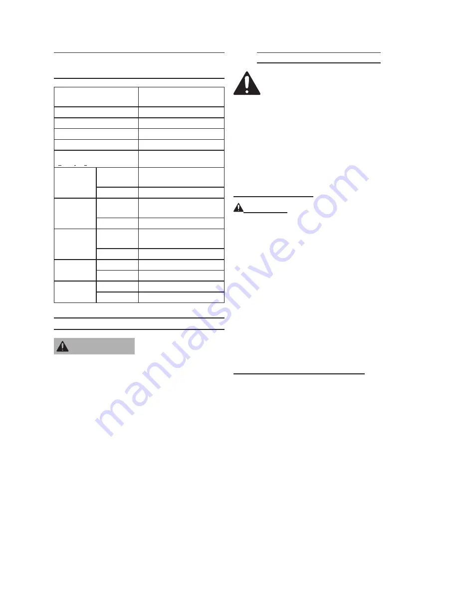
speciFications

Engine Type

Single Cylinder 4 stroke 

OHV

Battery Required

12V 18Ah

Bore x Stroke

68mm x 54mm

Displacement

196cc

Compression Ratio

8.5:1

Rotation 

viewed from PTO 

(power takeoff - the output shaft)

Counterclockwise

Fuel

Type

86+ octane unleaded 

gasoline

Capacity

0.95 Gallons

Engine Oil

Type SAE 10W30 above 32° F

5W30 at 32° F or below

Capacity

0.63 Quarts

Spark Plug

Type

F7RTC or

NGK F7TC

Gap

0.028 - 0.031”

Valve 

Clearance

Intake

0.15 ± 0.02 mm

Exhaust

0.20 ± 0.02 mm

Speed

Idle

 1,400 ± 150 RPM

Maximum  3,400 RPM

servicing


risk of serious 

personal injury 

from accidental starting.  turn 

the power switch of the 

equipment to its “oFF” 

position, wait for the engine to 

cool, and unplug the spark 

plug wire(s) before performing 

any inspection, maintenance, 

or cleaning procedures.
damaged equipment can fail, 

causing serious personal 

injury.  do not use damaged 

equipment.  if abnormal noise, 

vibration, or excess smoking 

occurs, have the problem 

corrected before further use.

Maintenance procedures

Many maintenance procedures, 

including any not detailed 

in this manual, will need to 

be performed by a qualified 

technician for safety.  if you 

have any doubts about your 

ability to safely service the 

equipment or engine, have a 

qualified technician service the 

equipment instead.

engine oil change

caution!

  Oil is very hot during opera-

tion and can cause burns.  Wait for 

engine to cool before changing oil.
Place a drain pan (not included) un-

1. 

derneath the crankcase’s drain plug.
Remove the drain plug and, if pos-

2. 

sible, tilt the crankcase slightly to help 

drain the oil out.  Recycle used oil.
Replace the drain plug and tighten it.

3. 

Refill the oil to the proper level follow

-

4. 

ing the instructions under the Starting 

the Engine section.

air Filter element Maintenance

The air cleaner cover is held in place 

1. 

by a wing nut or clamps.  Remove it.

Remove the air filter element.

2. 

cleaning:

3. 

For “paper” filter elements:


a. 

To prevent injury from dust and 

debris, wear ANSI-approved safety 

goggles, NIOSH-approved dust 

mask/respirator, and heavy-duty 

work gloves.  In a well-ventilated 

area away from bystanders, use 

pressurized air to blow dust out of 

the air filter.


Warning

Содержание 65075

Страница 1: ...d properly the ball could come loose while the Log Splitter is in motion possibly causing property damage serious personal injury or death Diagrams within this manual may not be drawn proportionally Due to continuing improvements actual product may differ slightly from the product described herein Distributed exclusively by Harbor Freight Tools 3491 Mission Oaks Blvd Camarillo CA 93011 Visit our w...

Страница 2: ...ter 14 Technical Specifications 15 Servicing 15 Maintenance Procedures 15 Engine Oil Change 15 Air Filter Element Maintenance 15 Spark Plug Maintenance 16 Fuel Filter Replacement if equipped 16 Cleaning Maintenance and Lubrication Schedule 17 After 20 Operation Hour Break in Period 17 After Every 25 Operation Hours 17 After Every 50 Operation Hours 17 After Every 100 Operation Hours 17 After Every...

Страница 3: ... Carburetor parts list diagram 31 Flywheel coil assembly parts list diagram 32 Control system parts list diagram 33 Air cleaner parts list diagram 34 Muffler parts list diagram 35 Fuel tank parts list diagram 36 Carbon canister assembly 37 Limited 1 year 90 Day warranty 38 Emission Control System Warranty 38 ...

Страница 4: ...on which if not avoided could result in minor or moderate injury NOTICE is used to address practices not related to personal injury CAUTION without the safety alert symbol is used to address practices not related to personal injury WARNING Read all instructions Failure to follow all instructions listed below may result in fire serious injury and or DEATH The warnings and precautions discussed in t...

Страница 5: ...om bined weight of the Log Splitter and logs Do not drive the Log Splitter on 6 roads or highways This product is not D O T compliant and is not road legal Always make sure the hitch coupler 7 is securely fixed to the vehicle before moving it If the Coupler is not se cured properly the link could come loose while the trailer is in motion possibly causing property damage SERIOUS PERSONAL INJURY or ...

Страница 6: ...for operations differ ent from those intended could result in a hazardous situation Do not operate the equipment with 21 known leaks in the engine s fuel sys tem This product contains or when used 22 produces a chemical known to the State of California to cause cancer and birth defects or other reproduc tive harm California Health Safety Code 25249 5 et seq WARNING The brass components 23 of this ...

Страница 7: ...quipment These carry impor tant information If unreadable or missing contact Harbor Freight Tools for a replacement Have the equipment serviced by a 6 qualified repair person using only identical replacement parts This will ensure that the safety of the equip ment is maintained Do not attempt any service or maintenance proce dures not explained in this manual or any procedures that you are un cert...

Страница 8: ...that the item is intact and undamaged If any parts are missing or broken please call Harbor Freight Tools at the number shown on the cover of this manual as soon as possible Set Up Instructions Read the entire Important Safety Information section at the beginning of this manual including all text under subheadings therein before set up or use of this product Risk of accidental starting resulting i...

Страница 9: ...Pin Clip 29 Horizontal transport hole Place Log Here Cylinder 1 Hex Nut 17 is attached to Hex Bolt 16 Vertical position locking hole FIGURE 2 FIGURE 3 Push Pin 26 Hydraulic Oil Fill Plug 37 with air inlet hole Close up of Push Pin 26 securing the Front Leg Assembly 11 to the bracket on the Oil Tank Assembly 10B Second Push Pin 26 secures Rail Assembly 2 and is removed for vertical log splitting Ho...

Страница 10: ...e the Push Pin 26 and Hair Pin Clip 29 and lift the Front Leg Assembly up so that it is parallel to the Rail Assembly Re place the Push Pin 26 and Hair Pin Clip 29 into the Horizontal Transport Hole shown just above the Oil Plug To connect the Rail Assembly 2 to 10 the Oil Tank Assembly insert a Hex Bolt 16 into the middle hole of the L shaped bracket on the Oil Tank Assembly Secure it with a Hex ...

Страница 11: ...3353 Engine diagram COMPONENTS CONTROL LOCATIONS 3 2 COMPONENTS CONTROL LOCATIONS THROTTLE LEVER MUFFLER SPARK PLUG AIR CLEANER FUEL VALVE LEVER CHOKE LEVER RECOIL STARTER STARTER GRIP IGNITION SWITCH FUEL FILLER CAP FUEL TANK OIL DRAIN PLUG OIL FILLER CAP DIPSTICK ...

Страница 12: ...Hydraulic Fluid Remove the Plug 37 and fill the tank 5 with Hydraulic fluid not included To check the fluid level remove the Dipstick 62 check the level then replace it The fluid should be at the upper notch of the Dipstick Be sure that a constant oil level of 2 5 gallons is maintained The hydraulic system must be vented 6 during operation or it may become vacuum locked and stop working To vent th...

Страница 13: ...urs of use After this period Change the engine oil Under normal operating conditions subsequent maintenance follows the schedule explained in the Mainte nance and Servicing section Equipment Operation 1 WARNING To avoid death or serious injury block each side of both wheels of the Log Splitter before starting a job In FIGURE 1 the Rail Assembly is 2 shown in Horizon tal mode for opera tion and tra...

Страница 14: ...ler There must be no play between the hitch ball and Hitch Coupler If there is play tighten the Adjustment Nut until no play is present If the Adjustment Nut is too tight the Handle will not lock Carefully read and follow the complete instructions in this manual BEFORE setup or use If the Coupler is not secured properly the ball could come loose while the trailer is in motion possibly causing prop...

Страница 15: ...lem corrected before further use Maintenance Procedures Many maintenance procedures including any not detailed in this manual will need to be performed by a qualified technician for safety If you have any doubts about your ability to safely service the equipment or engine have a qualified technician service the equipment instead Engine Oil Change CAUTION Oil is very hot during opera tion and can c...

Страница 16: ...hten until the gasket contacts the cylinder head then about 1 2 2 3 turn more Non gasket style Finger tighten until the plug contacts the head then about 1 16 turn more Apply dielectric spark plug boot 6 protector not included to the end of the spark plug and reattach the wire securely Fuel Filter Replacement if equipped WARNING Risk of fire or explosion Replace the fuel filter in a well ventilate...

Страница 17: ...and 100 operation hours should be performed at least yearly After Every 300 Operation Hours Clean fuel tank and carburetor a Clean carbon build up from combus b tion chamber Storage Wait for engine to cool then clean 1 engine with clean cloth When the equipment is to remain idle 2 for longer than 20 days prepare the engine for storage as follows Change engine oil and empty fuel a tank Either leave...

Страница 18: ...rts spinning with slight resistance Loosen the Castle Nut about 1 2turn from this point Insert a new Cotter Pin through the Castle Nut and the hole in the axle Bend the Pin back locking it and the Nut in place Bleeding the Hydraulic System If the Log Splitter begins to lose pow 1 er or splitting efficiency it may be a result of air becoming trapped in the hydraulic system Follow the steps below to...

Страница 19: ... Reinstall spark plug and set choke to start position Ignition spark Related Spark plug wire not connected 1 securely Spark plug electrode wet or dirty 2 Incorrect spark plug gap 3 Spark plug wire broken 4 Incorrect spark timing or faulty 5 ignition system Ignition spark Related Connect spark plug wire properly 1 Clean spark plug 2 Correct spark plug gap 3 Replace spark plug wire 4 Have qualified ...

Страница 20: ... unleaded gasoline Test replace fuel tank cap 3 Have qualified technician service 4 magneto Engine knocks Old or low quality gasoline 1 Engine overloaded 2 Incorrect spark timing deposit 3 buildup worn engine or other mechanical problems Fill fuel tank with fresh 86 octane 1 unleaded gasoline Do not exceed equipment s load 2 rating Have qualified technician diagnose 3 and service engine Engine bac...

Страница 21: ...ozzle 5 Dissolve by running warm water 6 through the injection tube Run clean water through injector 7 until clear Follow all safety precautions whenever diagnosing or servicing the equipment or engine PLEASE READ THE FOLLOWING CAREFULLY The manufacturer and or distributor has provided the parts list and assembly diagram in this manual as a reference tool only Neither the manufacturer or distribut...

Страница 22: ...9 Hex Bolt 5 16 2 3 4 1 20 Hex Nut 3 8 1 21 O ring Seal 1 22 Hex Bolt 1 2 1 3 4 4 23 Hex Nut 5 16 4 24 Spring Washer 5 16 8 25 Cotter Pin 2 26 Push Pin 2 27 Clevis Pin 1 28 Hair Pin Clip 2 29 Hair Pin Clip 2 5 2 30 Slide Holder 1 31 Hydraulic Tubing 1 Part Description Qty 32 High Pressure Hose 1 33 Return Hose 1 34 Inlet Hose 1 35 Hose Clamp 4 36 Male Connector 1 37 Oil Plug 1 38 High Pressure Fit...

Страница 23: ...Page 23 SKU 65075 For technical questions please call 1 800 444 3353 General Assembly diagram 10 ...

Страница 24: ...B Packing 1 7B Breathing Tube 1 8B Spark Plug 1 9B Cylinder Gasket 1 10B Muffler Gasket 1 11B Pin 2 12B Bolt 6x14 4 13B Bolt 8x55 4 14B Intake Bolt 2 15B Exhaust Bolt 2 16B Intake Valve Seat 1 17B Exhaust Valve Seat 1 18B Cylinder Head 1 When ordering parts for this component be sure to use the correct suffix Note Some parts are listed and shown for illustration purposes only and are not avail abl...

Страница 25: ...ider 1 8C Shaft Arm 1 9C Drain Plug Bolt 2 10C Washer 2 11C Washer 2 Part Description Qty 12C Clip 1 13C Ball Bearing 1 14C Oil Seal 1 15C O ring 1 16C Nut 1 17C Washer 1 18C R pin 1 19C Bolt 6x12 3 20C Shaft 1 21C Governor Assembly 1 22C Oil Alarm 1 When ordering parts for this component be sure to use the correct suffix Note Some parts are listed and shown for illustration purposes only and are ...

Страница 26: ...ick 1 3D Packing 2 4D Cover 1 5D Oil Seal 1 6D Bearing 1 7D Pin 2 8D Oil Filler Cap 1 9D Packing Case Cover 1 10D Oil Fill Assembly 1 11D Cap Assembly 1 When ordering parts for this component be sure to use the correct suffix Note Some parts are listed and shown for illustration purposes only and are not avail able individually as replacement parts ...

Страница 27: ...sembly 1 6E Bolt 2 7E Clip 2 8E Timing Gear 1 9E Gear 1 10E Crankshaft 1 11E First Ring 1 12E Second Ring 1 13E Oil Ring 2 14E Bushing Ring 1 15E Connecting Rod 1 16E Connecting Rod Cover 1 17E Key 1 When ordering parts for this component be sure to use the correct suffix Note Some parts are listed and shown for illustration purposes only and are not avail able individually as replacement parts ...

Страница 28: ...alve Spring Retainer 2 12F Valve Spring 2 13F Guide Seal 1 Part Description Qty 14F Camshaft Assembly 1 15F Reducer Pin 1 16F Reducer 1 17F Matching Block Pin 2 18F Matching Block 1 19F Flying Block Pin 1 20F Spring Pin 1 21F Flying Block Spring 1 22F Flying Block 1 23F Camshaft 1 24F Exhaust Valve 1 25F Intake Valve 1 When ordering parts for this component be sure to use the correct suffix Note S...

Страница 29: ...ring 2 7G Recoil Starter Reel 1 8G Recoil Starter Spring 1 9G Recoil Starter Knob 1 10G Fan Cover 1 11G Rope 1 12G Bolt 6x8 3 13G Bolt 6x10 4 14G Fan Cover 1 15G Switch Assembly 1 16G Recoil Starter 1 17G Fan Cover 1 18G Stop Switch Assembly 1 When ordering parts for this component be sure to use the correct suffix Note Some parts are listed and shown for illustration purposes only and are not ava...

Страница 30: ...m Part Description Qty 1H Bolt 6x20 1 2H Side Plate 1 3H Bolt 6x8 2 4H Shroud 1 5H Side Plate 1 6H Grommet 1 When ordering parts for this component be sure to use the correct suffix Note Some parts are listed and shown for illustration purposes only and are not avail able individually as replacement parts ...

Страница 31: ...14J Drain Bolt Gasket 1 15J Fuel Strainer Cup 1 16J Fuel Strainer Cup Packing 1 17J Fuel Packing 1 18J Lever 1 Part Description Qty 19J Lever Spring 1 20J Setting Plate 1 21J Screw 3x8 2 22J Jet Set 1 23J Pilot Jet Set 1 24J Choke Lever Assembly 1 25J Choke Lever 1 26J Choke Lever Pin 1 27J Choke Set 1 28J Screw 1 29J Screw Spring 1 30J Throttle Stop Screw 1 31J Air Cleaner 1 32J Carburetor Packin...

Страница 32: ...1 4K Stop Switch Cord 1 5K Bolt 6x30 2 6K Flywheel Cover 1 7K Charge Coil Assembly 1 8K Cooling Fan 1 9K Starter Pulley 1 10K Nut 1 11K Flywheel 1 12K Charge Coil 1 13K Bolt 6x35 2 14K Cord Clamp 1 15K Bolt 6x8 1 When ordering parts for this component be sure to use the correct suffix Note Some parts are listed and shown for illustration purposes only and are not avail able individually as replace...

Страница 33: ...ly 1 9M Nut 1 10M Fixing Plate 1 11M Washer 1 Part Description Qty 12M Washer 1 13M Retainer Assembly 1 14M Spring 1 15M Screw 5x35 16M Cable Return Spring 1 17M Control Handle 1 18M Screw 5x25 1 19M Back Plate 1 20M Screw 4x6 1 21M Locking Ring 1 22M Clip 1 When ordering parts for this component be sure to use the correct suffix Note Some parts are listed and shown for illustration purposes only ...

Страница 34: ...x20 1 7N Nut 6mm 2 8N Nut 2 9N Air Cleaner Cover 1 Part Description Qty 10N Air Cleaner Element Assembly 1 11N Grommet 1 12N Outer Filter 1 13N Element 1 14N Noise Silencer 1 15N Air Cleaner Assembly 1 16N Cover 1 17N Screw 2 When ordering parts for this component be sure to use the correct suffix Note Some parts are listed and shown for illustration purposes only and are not avail able individual...

Страница 35: ...t diagram Part Description Qty 1P Muffler Assembly 1 2P Gasket 1 3P Air Valve 1 4P Bolt 2 When ordering parts for this component be sure to use the correct suffix Note Some parts are listed and shown for illustration purposes only and are not avail able individually as replacement parts ...

Страница 36: ...rts list diagram Part Description Qty 1R Fuel Tank Assembly 1 2R Valve 1 3R Gasket 1 When ordering parts for this component be sure to use the correct suffix Note Some parts are listed and shown for illustration purposes only and are not avail able individually as replacement parts ...

Страница 37: ...rt Description Qty 1S Shroud 1 2S Mount 1 3S Carbon Canister 1 4S Canister Vent 1 5S Canister Vent 1 When ordering parts for this component be sure to use the correct suffix Note Some parts are listed and shown for illustration purposes only and are not avail able individually as replacement parts ...

Страница 38: ...epaired products at our expense but if we determine there is no defect or that the defect resulted from causes not within the scope of our warran ty then you must bear the cost of returning the product This warranty gives you specific legal rights and you may also have other rights which vary from state to state 3491 Mission Oaks Blvd PO Box 6009 Camarillo CA 93011 800 444 3353 Emission Control Sy...

Страница 39: ...e filed in accordance with the provi sions of the HFT warranty policy explained in the box at the top of the previous page HFT shall not be liable for any loss of use of the engine for any alternative usage for any damage to goods loss of time or inconvenience Warranty coverage shall also be excluded for any part which fails malfunctions or is damaged due to failure to follow the maintenance and o...

Отзывы: