Greer Company
Crane Systems
GREER COMPANY
1918 E. Glenwood Place, Santa Ana, CA 92705 Tel: (714) 259-9702 Fax: (714) 259-7626
MG
®
400 Computer Training Manual PN W424900 - 11/07/02
6 of 18
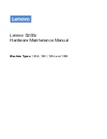
Terminal Block Markings
Terminal blocks are marked as shown in the graphic to
the right. Note that there are multiple Drive Voltage
terminals (DR+ and DR-) in different locations. Note that
these terminals are all common on the computer board
assembly. The same is true of any OV or +VP terminals.
For example, checking the drive voltage on TB2 should
provide exactly the same readout as at any drive voltage
terminal on TB3.
AIN2 and AIN3 are typical voltages checkpoints for
analog input signals from the boom angle and length
pots. These signals will vary depending on how the unit
is operated at the time the reading is taken. Refer to the
maintenance manual for further definition of terminal
blocks.
Because the drive voltages are all common, any analog
sensor can be suspect. If, for example, drive voltage is
low, and +15 V is within tolerance, each of the analog
sensors must be removed, one at a time, until the sensor
that is causing the voltage to sag is located and replaced. If the voltage continues to sag, the
processor board should be replaced as the drive voltage power supply is integrated into the
processor board.
This is a simple process of elimination, which will help pinpoint a failing sensor, an abrasion, or a
pinch in a wire or loom. All wiring could become suspect at this time and should be carefully
checked. Output tests can also be run at the sensors by attaching the voltage meter at the
sensor output and watching as the sensor is extended or raised. Voltage skips or gaps can be
detected using this technique.
+D R
0V
-D R
+D R
0V
+D R
-D R
-D R
0V
AIN 1
AIN 0
-D R
AIN 5
AIN 6
AIN 2
+VP
0V
+D R
+D R
TX0-
TX0+ AIN 4
TX1+
TX1-
-D R
0V
AIN 3
+VP
+VP
OV
OV
OV
OV
OV
TB2
TB3
TB4
Voltage Checks