12
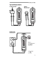
Typical Measurements
RCD Check (GT-95e only)
1.
Consult the RCD
manufacturer’s installation
instructions to determine
that the RCD is installed in
accordance with the
manufacturer’s specifica-
tions.
2.
Check for correct wiring of
the receptacle and all
remotely connected
receptacles on the branch
circuit.
3.
Operate the test button on
the RCD installed in the
circuit. The RCD must trip.
• If the RCD does not
trip, do not use the
circuit. Consult an electrician.
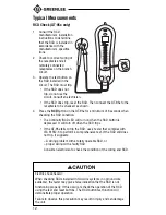
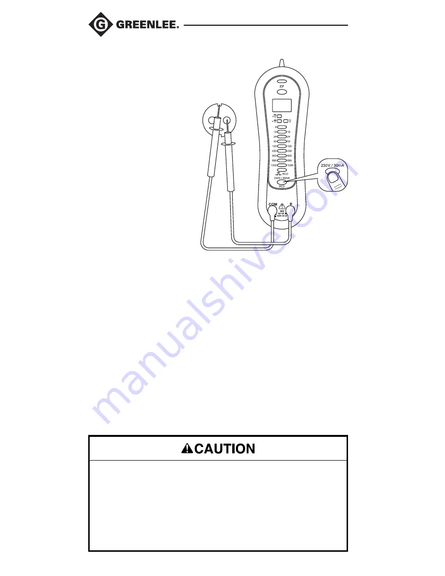
• If the RCD does trip, reset the RCD. Then connect the GT-95e to the
receptacle to be checked, as shown.
4.
Press the RCD button on the GT-95e for a minimum of 6 seconds when
checking the RCD condition.
• The Continuity/RCD LED will turn on when the RCD button is
depressed. It will turn off when the RCD trips.
• If the GT-95e fails to trip the RCD, use a tester that complies with
IEC 61557-6 to perform a comprehensive test. If the RCD still does
not trip, it suggests:
– A wiring problem with a totally operable RCD, or
– proper wiring with a faulty RCD.
Consult an electrician to check the condition of the wiring and RCD.
Electric shock hazard:
When checking RCDs installed in two-wire systems (no ground wire
available), the tester may give a false indication that the RCD is not
functioning properly. If this occurs, recheck the operation of the RCD
using the test and reset buttons. The RCD button test function will
demonstrate proper operation.
Failure to observe this precaution may result in injury and can damage
the unit.


