INSTRUCTION MANUAL
43180
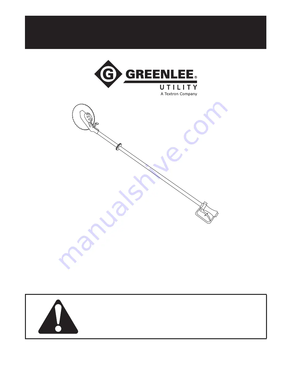
Overhead Circular Saw
99913097 REV 11
© 2010 Greenlee Textron Inc.
10/10
Read
and
understand
all of the instructions and
safety information in this manual before operating
or servicing this tool.
Register this product at www.greenlee.com


