


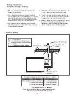
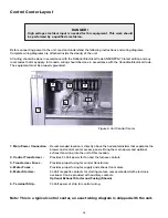
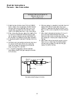
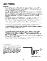

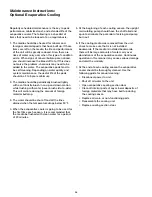
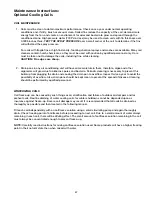

From
Gas
Gas Cock
1/8 in. Plugged
6 in. Trap
Ground Joint Union
To Controls
23
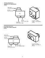
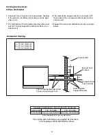
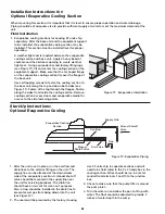
1. Single furnaces (furnace input 100 to 400 MBH)
have a single
3
⁄
4
inch connection. Double furnaces
(furnace input 500 to 800 MBH) have two
3
⁄
4
inch
connections, and triple furnaces (furnace input
1050 to 1200 MBH have three
3
⁄
4
inch connections.
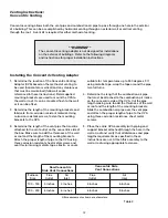
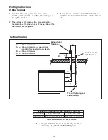
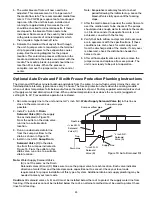
2. When connecting the gas supply, the length of the
run must be considered in determining the pipe
size to avoid excessive pressure drop. Refer to a
Gas Engineer’s Handbook for gas pipe capacities.
3. A drip leg should be installed in the pipe run to the
unit.
4. Install an easily accessible ground joint union and
a manual shut off valve (these are required by
some local codes) for emergency shut off and
easy servicing of the controls.
5. A
1
⁄
8
inch NPT plugged tap shall be installed
immediately ahead of the gas supply connection
to the furnace.
6. After gas piping is completed, carefully check all
piping connections for gas leaks. Use soap
solution or equivalent for testing. DO NOT use a
flame or other source of ignition to check for gas
leaks.
7. When leak testing pressures above 14 in. wc (
1
⁄
2
psi), close the field installed shutoff valve,
disconnect the furnace and its gas train from the
gas supply line, and plug the supply line before
testing.
8. When leak testing at pressures equal to or less
than 14 in. wc (
1
⁄
2
psi) close the field-installed
shutoff valve to isolate the unit from the gas
supply line before testing.
Recommended Piping to Controls
Gas Supply Pressure Requirements
Natural: 6 to 14 in. wc
LP: 11 to 14 in. wc
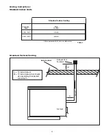
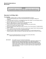
Start-Up Instructions:
Furnace - Gas Connection
Manual Shut
Off Valve
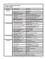
Содержание IGX
Страница 38: ...38 Documentation Date Problem Resolution...


