background image

Determining Static Pressure (Ps)

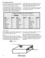
The pressures generated by fans in ductwork are very small.
Yet, accurately estimating the static pressure is critical to
proper fan selection.

Fan static pressure is measured in inches of water gauge.
One pound per square inch is equivalent to 27.7 in. of water
gauge. Static pressures in fan systems are typically less
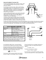
than 2 in. of water gauge, or 0.072 Psi.  The drawing to the
right illustrates how static pressures are measured in
ductwork with a manometer.

A pressure differential between the duct and the atmosphere
will cause the water level in the manometer legs to rest at
different levels. This difference is the static pressure
measured in inches of water gauge.

In the case of the exhaust fan at right, the air is being drawn
upward through the ductwork because the fan is producing
a low pressure region at the top of the duct. This is the same
principle that enables beverages to be sipped through a straw.

The amount of static pressure that the fan must overcome depends on the air velocity in the ductwork, the number
of duct turns (and other resistive elements), and the duct length. For properly designed systems with sufficient
make-up air, the guide lines in the table below can be used for estimating static pressure:

To calculate the system losses, one must know the
ductwork system configuration (see Ductwork figure).

This duct is sized for air velocities of 1400 feet per minute.
Referring to the static pressure chart, that will result in
about 0.3 in. per 100 feet. Since we have 10 feet of total
ductwork, our pressure drop due to the duct is:

.3 in. x 10 ft. = .03 in.

100 ft.

There is also a 0.08 in. pressure drop for each resistive
element or fitting. For this example, there are 5 fittings:

one grill, two duct turns, one damper and louvers in
the wall of the office. The total pressure drop for
fittings is:

5 x 0.08 in. = 0.4 in.

Therefore, the total pressure drop is:

0.03 in. + 0.40 in. = 0.43 in.

For convenience in using selection charts, round this
value up to the nearest 1/8 in., which would be 0.50 Ps.

STATIC PRESSURE GUIDELINES

Non-Ducted  

0.05 in. to 0.20 in.

Ducted

0.2 in. to 0.40 in. per
100 feet of duct (assuming duct
air velocity falls within 1000-1800
feet per minute)

Fittings

0.08 in. per fitting
(elbow, register, grill, damper, etc.)

Kitchen Hood Exhaust

0.625 in. to 1.50 in.

Important: Static pressure requirements are significantly affected
by the amount of make-up air supplied to an area. Insufficient
make-up air will increase static pressure and reduce the amount of
air that will be exhausted. Remember, for each cubic foot of air
exhausted, one cubic foot of air must be supplied.

17

Exhaust Fan

Ductwork

Содержание 240XP-CUB

Страница 1: ...Fan Selection Application Based Selection Performance Theory...

Страница 2: ...e and static pressure This section also interprets Greenheck model numbers and illustrates the relationship between fan speed and airflow Section Two covers the basics of fan selection determining the...

Страница 3: ...N FAN APPLICATION Basic Overview 9 Commercial Kitchen Ventilation 10 General Commercial Ventilation 12 High Static Pressure Ventilation 15 Determining CFM 16 Determining Static Pressure 17 Sound Level...

Страница 4: ...B Model is G rpm is 1140 Nominal Wheel Dia 12 in The table below lists model designation suffixes for motor horsepower and fan rpm Belt Drive Direct Drive Suffix Motor hp Suffix Fan rpm 6 1 6 A 1725 4...

Страница 5: ...1 cfm the fan will be running at 1260 rpm At 1269 cfm the fan will be running at 1635 rpm Therefore there is an rpm for this model that will correspond to 1000 cfm obviously somewhere within the 1260...

Страница 6: ...rpm D 1300 rpm G and 1050 rpm E Changing a motor lead is all that is necessary to change speeds When selecting a model with 3 speed motors it is recommended that the G speed be chosen whenever possib...

Страница 7: ...1 2 hp motor RSF 90 4 1 4 hp motor is not recommended for this job Matching a Specification There will be times when a Greenheck model will have to be matched to a competing manufacturer s unit To ai...

Страница 8: ...WD CW Fumex WFX Domex WX WA WB PDU W PW CWD VWDK VWDB CWD CWF CDU WDC DU CWB GWB ACWB CWB TWB Fumex WFXB Domex WCB WLB PNU W PWB NBTD NBRTD UL 762 VWBK VWBB CWB CBU WBC NCA SP Gemini GC Zephyr Z RA TD...

Страница 9: ...fan model and the air volume flow rate cfm Other considerations include the resistance to airflow static pressure or Ps and sound produced by the fan Sones Occasionally a customer will require a fan t...

Страница 10: ...2 listed for restaurant applications and for operation with air temperatures up to 300 F Recommended Supply Fans The above models are designed to provide efficient economical make up air to replenish...

Страница 11: ...s The National Fire Protection Association specifies minimum distance criteria for restaurant exhaust and supply fans as shown below 10 ft Horizontal Separation 1 Roof deck to top of exhaust fan windb...

Страница 12: ...sting relatively clean air at temperatures up to 130 F Motors are out of the airstream Direct drive sizes 60 95 are equipped with 3 speed motors for maximum airflow flexibility All direct drive units...

Страница 13: ...Typical Commercial Ventilation Installations 13...

Страница 14: ...ount as well as exhaust or supply However because the motors are mounted in the airstream these models are not recommended for temperatures above 110 F Model SB Belt Drive Propeller Sidewall 3 600 85...

Страница 15: ...generated by long or complex duct systems especially when capture hoods are present Both models can be used for either exhaust or supply Model SWB is designed to be mounted indoors or outdoors while...

Страница 16: ...rmal area usage select a lower number in the range to change the air more quickly For moderate climates with lighter usages select a higher number in the range To determine the cfm required to adequat...

Страница 17: ...an be used for estimating static pressure To calculate the system losses one must know the ductwork system configuration see Ductwork figure This duct is sized for air velocities of 1400 feet per minu...

Страница 18: ...8 0 76 15 9 0 77 14 9 0 77 14 8 0 77 14 7 0 78 2318 2104 1875 1587 8 9 0 18 8 5 0 19 8 3 0 19 7 8 0 19 2555 2359 2162 1932 1624 10 6 0 24 10 1 0 25 9 7 0 26 9 4 0 26 8 8 0 25 2909 2737 2567 2382 2176...

Страница 19: ...essure levels For example a sound level of 10 sones is twice as loud as 5 sones Refer to the Suggested Limits for Room Loudness chart to determine the acceptable sone range for the application As a ge...

Страница 20: ...w into the fan Wheel Rotation A common problem is wheel rotation in the wrong direction For centrifugal fans incorrect wheel rotation will provide some airflow However the airflow will be far below th...

Страница 21: ...application The information in this section is useful once the fan has been selected and installed on the job The fan curves and system resistance curves below will help to solve fan performance probl...

Страница 22: ...ossible to move 2000 cfm at only 0 25 in Ps For any given system every cfm requires a unique Ps This series of cfm Ps points forms a system resistance curve such as the one above Once the system resis...

Страница 23: ...that as we doubled our airflow from 1000 cfm to 2000 cfm the Ps went up from 0 25 in to 1 0 in It must be kept in mind that we are not changing the system only increasing fan speed Therefore we must...

Страница 24: ...s in those sections on how to apply these equations The third equation relates horsepower to rpm The change in horsepower can be determined when the rpm is increased by 25 This is shown below BhpNew 1...

Отзывы: