background image

Important safety instructions...................................................................

1-3

Safety instructions

Radio interference statement for communications

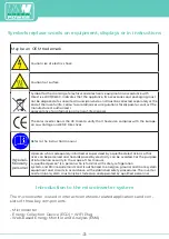
Symbols to replace words on equipment, displays and instructions

Introduction to the microinverter system............................................

3-5

How microwaves maximize energy production from PV installations

Less unreliable microinverters

Easy installation

Introduction to the microinverter...........................................................

5

Installation of a microinverter system...................................................

6-9

Additional PV installation components

Required parts and tools

Installation procedures

Microinverter System User Manual.........................................................

9-10

Troubleshooting.............................................................................................

10-12

Status indicator and error reporting

Troubleshooting a malfunctioning microinverter

Indicator............................................................................................................

13

Microinverter replacement........................................................................

13

Technical data................................................................................................

13-15

Datasheets

MPL MicroPV1300-ZB/MPLMicroPV1300-PLC

MPL MicroPV600-ZB/MPLMicroPV600-PLC

Wiring diagram..............................................................................................

16-21

Example connection diagrams

Содержание 1300G

Страница 1: ...Installation Instructions User Manual Microinverter connected to the grid photovoltaic and type designations ...

Страница 2: ...tallation Introduction to the microinverter 5 Installation of a microinverter system 6 9 Additional PV installation components Required parts and tools Installation procedures Microinverter System User Manual 9 10 Troubleshooting 10 12 Status indicator and error reporting Troubleshooting a malfunctioning microinverter Indicator 13 Microinverter replacement 13 Technical data 13 15 Datasheets MPL Mi...

Страница 3: ...perly Use extreme caution when performing this task WARNING This indicates information important to the optimized operation of the microinverter Follow these instructions Safety instructions DO NOT disconnect the photovoltaic module from the microinverter without first disconnecting the mains power Only qualified professionals should install or replace microinverters Perform all electrical install...

Страница 4: ...ccur in a par ticular installation If this equipment does cause harmful interference to radio or television reception the following measures may solve the problems A Reposition the receiving antenna and keep it away from the equipment B Consult the dealer or an experienced radio TV technician for help Changes or modifications not expressly approved by the party responsible for compliance could voi...

Страница 5: ...e and EMC Directives Refer to the instruction manual Wykwali fikowany personel A person who is adequately informed or supervised by a qualified electrician so that risks can be perceived and hazards posed by electricity can be avoided For the purpose of information security in the scope of this manual a qualified person is a person who is familiar with safety refrigeration system and EMC requireme...

Страница 6: ...0 PLC MPL MicroPV 1300 ZB or MPL Micro PV 1300 PLC This integrated system improves safety maximizes solar energy use increases system reliability and simplifies the design installation maintenance and ma nagement of a photovoltaic system 4 ...

Страница 7: ...nd different types The ground wire PE of the AC cable is connec ted to the housing inside the microinverter potentially eliminating the use of a ground wire check local ordinance The MPL MicroPV Gate energy storage device MECD is installed by plugging it into any wall outlet and providing a broadband Ethernet connection to a router or modem Once installed and set up see ECD manual the entire netwo...

Страница 8: ...echnical documentation and on the microinverter itself WARNING Please note that there is a risk of electric shock when installing this device WARNING Do not touch any live parts on the system including the photovoltaic system when the system has been connected to the mains ATTENTION We strongly recommend installing surge protection devices for the photovoltaic AC switchgear Additional installation...

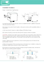
Страница 9: ...l wiring before connecting to the AC cable to make sure they match Incorrect wiring can irreparably damage the microinverters this problem is not covered under warranty Step 2 Mount the microinverter on the mounting structure or frame of the photovoltaic module a Mark the position of the microinverter on the structure in relation to the pho tovoltaic module junction box or other components b Mount...

Страница 10: ...m of the microinverter to allow adequate airflow Step 3 Connect serial microinverters photovoltaic modules to each DC input 600 ZB PLC series connection in one branch 1300 ZB PLC series connection in one branch a Check the microinverter technical data page page 18 for the maximum allowable number of microinverters in each chain b Connect the male AC connector of the microinverter to the female con...

Страница 11: ...s the cables are connected which will show that the microinverter is working properly This entire check function will start and stop within 5 seconds of connecting the unit so keep an eye out for these lights when connecting the DC cables Microinverter System User Manual To operate a microinverter PV system 1 Turn on the AC breaker on each AC circuit of the microinverter 2 turn on the main AC brea...

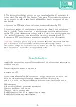
Страница 12: ...nformation WARNING When AC power is applied approximately 0 1 A of current and 25VA W of power can be measured for each microinverter using a meter This current and power are reactive The inverters are NOT operating After more than 60 seconds the inverters will begin to operate Troubleshooting Qualified personnel can use the following steps if the photovoltaic system is not working properly Status...

Страница 13: ...ving problems b The microinverter itself is working fine but has ECD communication pro blems The following items address microinverter problems not communication problems addressed in the ECD manual A quick way to determine if it is a microinverter or ECD communication problem 1 diagnosis from the microinverter side Red light either flashing or continuous light on the microinverter or no light at ...

Страница 14: ...erter is generating power Reconnect the DC module connectors and watch for three short LED flashes 3 Check the AC branch circuit connection between all microinverters 4 Verify that each inverter is energized as described in the previous step 5 Verify that any AC circuit breaker is functioning properly and is closed 6 Check that the DC voltage of the photovoltaic module is within the allowable rang...

Страница 15: ...r in the cabi net Remember to watch the flashing LED light as soon as the new microinver ter is connected to the DC cables 3 Connect the AC cable of the replacement microinverter 4 Close the overcurrent circuit breaker and check the operation of the replace ment microinverter Microinverter replacement Technical data WARNING Make sure that the voltage and current specifications of the photo voltaic...

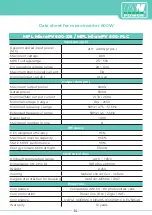
Страница 16: ... frequency range 50Hz 47 5 51 5Hz Extended frequency range 50Hz 45 55Hz Power factor 0 90 Maximum number in line 8 Efficiency CEC weighted efficiency 95 Maximum inverter capacity 96 5 Static MPPT performance 99 Energy consumption at night 50mW Mechanical data Ambient temperature range 40 C 65 C Dimensions W x H x D 188 x 164 x 29mm Weight 2 2kg Cooling Natural convection no fans Degree of protecti...

Страница 17: ...l frequency range 50Hz 47 5 51 5Hz Extended frequency range 50Hz 45 55Hz Power factor 0 95 Maximum number in line 48 Efficiency CEC weighted efficiency 95 Maximum inverter capacity 96 5 Static MPPT performance 99 Energy consumption at night 50mW Mechanical data Ambient temperature range 40 C 65 C Dimensions W x H x D 450 x 455 x 35mm Weight 6 5kg Cooling Natural convection no fans Degree of protec...

Страница 18: ...nnection diagram BLACK L2 RED L1 YELLOW NEUTRAL Counter Concentrator Grounding Ethernet cable connected to broadband router Annotations If you are using our zigbee type you only need one ECD If you are using our PCL type you should install three ECDs per phase AC distribution board 16 ...

Страница 19: ...PV 600 ZB MPL MicroPV 600 PLC Example of one phase connection diagram BLACK L2 RED L1 YELLOW NEUTRAL Counter Concentrator Grounding AC distribution board MPL MicroPV Gate WiFi plug ethernet cable connect to the router broadband 17 ...

Страница 20: ...re using our zigbee type you only need one ECD If you are using our PLC type you need to install three ECDs in each phase BLACK L2 RED L1 YELLOW NEUTRAL Counter Concentrator Grounding AC distribution board MPL MicroPV Gate WiFi plug ethernet cable connect to the router broadband WiFi plug 18 ...

Страница 21: ...gram Example of one phase connection diagram BLACK L2 RED L1 YELLOW NEUTRAL Counter Concentrator Grounding AC distribution board MPL MicroPV Gate WiFi plug ethernet cable connect to the router broadband WiFi plug 19 ...

Отзывы: