background image

BACnet Protocol Gateway


15 

Parameters that can be set: gateway IP address (IP address setting: numbers 

of master unit can’t all be 0; if they are all 0, it indicates the whole network, such as 

192.168.0.0

numbers of master unit can’t all be 1; if they are all 1, it indicates 

broadcast address, such as 192.168.0.255. It is not suggested to be set by users. 

Otherwise, the gateway pages will unable to access), Gateway subnet mask, 

defaulted gateway,device name and device ID. Users can configurate it by 

themselves according to actual circumstances. 

Default parameters: 


Access 

platform:Third-party; 


Access protocol:BACnet IP; 


Communication port :47808; 


OutTime:1000(ms). 

After the parameter setting is completed, click Save and restart the gateway to 

complete the configuration. 

Caution!  The default parameters should not be changed. Otherwise, the 

gateway may not work normally. 


Содержание ME30-44/D2 B

Страница 1: ...Owner s Manual Original Instructions BACnet Protocol Gateway Model ME30 44 D2 B ...

Страница 2: ... functions introduced in this manual are only applicable to specific products all the illustrations and information in this manual are only for reference and the control interface should be subject to the actual interface 3 In order to better meet the customers demand our company will improve the product continuously and we have the right to conduct necessary modification at any time due to the re...

Страница 3: ... for Gateway 4 5 1 Interface 4 5 2 LED Display 5 5 3 Button 6 5 4 DIP Switch 6 6 Application 7 6 1 Building Management System BMS 7 6 2 Internet Topological Graph 8 7 Product Installation 9 7 1 Product Size and Spatial Size for Electric Control Cabinet Installation 9 7 2 Gateway and BMS Communication Connecting Method 10 8 Attachment A TCP IP Setting 16 9 Attachment B Applicable Model 20 ...

Страница 4: ... severe damage or death to people This sign indicates that the items must be observed Improper operation may cause damage to people or property WARNING This product can t be installed at corrosive inflammable or explosive environment or the place with special requirements such as kitchen Otherwise it will affect the normal operation or shorten the service life of the unit or even cause fire hazard...

Страница 5: ...ted range it would result in a fire hazard or even damages to this device For PLUGGABLE EQUIPMENT the socket outlet shall be installed near the equipment and shall be easily accessible Do install this device inside the electric control cabinet which is located indoor and then is locked Do install this device where it will not be subject to the electromagnetic interference or heavy dust CAUTION Be ...

Страница 6: ...ted in Attachment B The following BACnet protocol gateway ME30 44 D2 B is shorted as gateway 3 2 Parameter Specifications 3 2 1 Gateway TCP IP Parameter Default IP Address 192 168 0 200 Subnet Mask 255 255 255 0 Default gateway 192 168 0 1 CAUTION After the TCP IP parameters are altered the gateway should be restarted then the parameters can come into effect 4 Parts and Assembly This kit includes ...

Страница 7: ...cable in this device please do not connect to electric appliance otherwise it may cause malfunction of gateway 5 1 3 Communication Interface CAN comm port this device will not use this communication interface temporarily RS485 1 comm port connect to the unit s or the connection between adjacent gateways RS485 2 comm port this device will not use this communication interface temporarily USB and SD ...

Страница 8: ... LED indicator is mainly consist of two parts status indicator run power and communication indicator CAN and RS485 The following table is the working status of each indicator CAN RX This device does not use this LED indicator TX This device does not use this LED indicator RS485 1 RX When the gateway receives data on the 485 bus it blinks TX When the gateway sends data to the 485 bus it blinks RS48...

Страница 9: ... setting area is consisting of function DIP switch code 5 4 1 Diagram of Dial up Machine 5 4 2 The 2st Lever of Functional DIP Switch 485 Bus Matched Resistance Setting The 2nd dial code of the function dialer is used for setting the matching resistance of the gateway of 485 bus When the controller is at the beginning end of the 485 bus the controller needs to be set to be with matching resistance...

Страница 10: ... code Fig 5 6 Schematic diagram of scenes that no need to set DIP switch code 6 Application 6 1 Building Management System BMS This gateway has provided BACnet standard protocols which can connect to building management system BMS It can monitor RS485 protocol Gree unit by Building Management System through the gateway ...

Страница 11: ...tion 485 bus 485 bus The wire indicated by L2 in fig 6 1 is 485 bus One 485 bus can connect 255 units at the most Cable The wire indicated by L2 in fig 6 2 is the normal cable The gateway can be connected to BMS by the cable Units quantity that can be connected to the gateway One gateway can connect 255 units at the most ...

Страница 12: ...ting of Gateway is correct Otherwise there will be communication malfunction 3 Ensure that the communication cord has connected to the correct interface Otherwise there will be communication malfunction 4 Do not place Gateway in direct sunlight or high temperature and humid environment Place it in the central control cabinet 7 1 2 Spatial Size for Electric Control Cabinet Installation Gateway shal...

Страница 13: ...nce 7 2 Gateway and BMS Communication Connecting Method 7 2 1 Material Selection for Communication Iine 1 Model selection of Gateway and BMS communication line shall use standard Ethernet communication line the length of network cable between gateway and router computer switchboard etc shall not exceed 80m 2 Communication line model selection for Gateway and AC unit Wire type L m Communication lin...

Страница 14: ...and BMS Fig 7 3 Connecting method between gateway and router 2 Communication connection between Gateway and AC units n is the quantity of unit s n 255 Fig 7 4 Connecting method of gateway NOTICE All communication connection lines under Gateway must be in series connection star connection shall not be adopted ...

Страница 15: ... cross connection network cable Gateway shall directly connect to PC Fig 7 5 Gateway connects to personal computer directly 2 Adopt parallel network cable Gateway shall go through router to connect to PC Fig 7 6 Gateway connects to personal computer via router 2 Communication line connection between Gateway and AC units Models of U Match Rooftop unit old models please refer to Annex B ...

Страница 16: ...rs of gateway should be set Before setting the parameters of gateway please set the IP address of PC as the same with the IP address in the same network segment of gateway as refer to appendix A and then open the browser IE10 and above version Firefox or Google input the default IP address of gateway http 192 168 0 200 default user name admin password 123456 as shown below Fig 7 7 Log on interface...

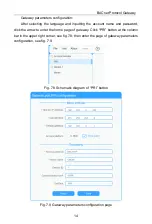
Страница 17: ...he account name and password click the arrow to enter the home page of gateway Click PRI button at the column bar in the upper right corner see fig 7 8 then enter the page of gateway parameters configuration see fig 7 9 Fig 7 8 Schematic diagram of PRI button Fig 7 9 Gateway parameters configuration page ...

Страница 18: ...ted to be set by users Otherwise the gateway pages will unable to access Gateway subnet mask defaulted gateway device name and device ID Users can configurate it by themselves according to actual circumstances Default parameters Access platform Third party Access protocol BACnet IP Communication port 47808 OutTime 1000 ms After the parameter setting is completed click Save and restart the gateway ...

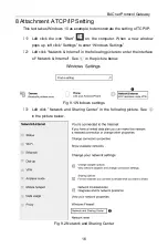
Страница 19: ... on the computer When a new window pops up left click Settings to enter Windows Settings 2 Left click Network Internet in the following picture to enter the interface of Network Internet See in the picture below Fig 9 1 Windows settings 3 Left click Network and Sharing Center in the following picture See in the picture below Fig 9 2 Network and Sharing Center ...

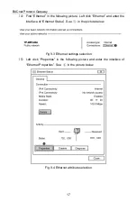
Страница 20: ...lick Ethernet and enter the interface of Ethernet Status See in the picture below Fig 9 3 Ethernet settings selection 5 Left click Properties in the following picture and enter the interface of Ethernet Properties See in the picture below Fig 9 4 Ethernet attribute selection ...

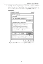
Страница 21: ...rotocol Version 4 TCP IPv4 See in the picture below Then left click Properties as shown in the picture to enter the interface of Properties of Internet Protocol 4 TCP IPv4 See in the picture below Fig 9 5 Internet Protocol Version 4 TCP IPv4 Properties ...

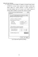
Страница 22: ...otocol Version 4 TCP IPv4 as shown below change the IP address subnet mask default gateway as required address of network equipment for connecting Gateway must be the same as the network address of Gateway ME30 44 D2 B Generally DNS remains unchanged Fig 9 6 Ethernet IP parameter settings ...

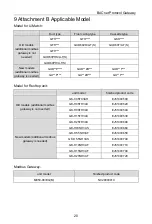
Страница 23: ...ZD GUD T GU P GU ZD GU T Model for Rooftop unit unit model finished product code Old models additional modbus gateway is not needed GK C05TC3AH EJ51000500 GK H05TH3AX EJ51000520 GK H08TH3AX EJ51000540 GK H15TH3AX EJ51000530 New models additional modbus gateway is needed GK H25TH3AX EJ51000690 GK H03NH3AS EJ51000660 GK H5 5NH3AF EJ51000650 GK H5 5NH3AS EJ51000740 GK H10NH3AF EJ51000710 GK H15NH3AF ...

Страница 24: ......
Отзывы: