background image

AIR COOLED SCROLL CHILLER                                                MAINTENANCE 


36

4

Internal Protection of Compressor 


5

High Noise of Compressor   


Содержание LSQWF130M/N-M

Страница 1: ...Air Cooled Scroll Chiller Service Manual T1 R407C 50Hz GREE ELECTRIC APPLIANCES INC OF ZHUHAI ...

Страница 2: ...ter 12 2 3 Antifreezing Protection Control 14 2 4 Control of 4 Way Valve 14 2 5 Control of Water Pump 14 3 WIRED REMOTE CONTROLLER 14 3 1 Function 14 3 2 Operation View 14 3 3 Display View 16 3 4 Menu Structure of Controller 17 3 5 Sketch map of DIP switch 18 INSTALLATION 20 1 BEFORE INSTALLATION 20 2 INSTALLATION SITE 20 3 CAUTIONS FOR INSTALLATION 20 4 MACHINE FOOTPRINT 20 5 DIMENSION DATA 22 6 ...

Страница 3: ...2 1 TROUBLE TABLE 32 2 FLOW CHART OF TROUBLESHOOTING 33 4 EXPLODED VIEWS AND PART LIST 46 ...

Страница 4: ...GREE COMMERCIAL AIR CONDITIONER AIR COOLED SCROLL CHILLER 1 PRODUCT ...

Страница 5: ...QWRF130M N M 120 34 130 37 400V 3N 50Hz R407C Note 1Ton 12000Btu h 3 517Kw 2 NOMENCLATURE LS QW R F 80 M N M 1 2 3 4 5 6 7 8 NO Description Options 1 Water Chiller 2 Compressors Type Hermetic Scroll Compressors 3 Function Code Omitted Cooling Only R Heat Pump 4 Air Cooled 5 Nominal Cooling Capacity 65 60 kw 80 76kw 130 120kw 6 Modular 7 Development series number 8 Voltage Code M 380V 3N 50Hz 400V ...

Страница 6: ... a compact design and small footprint A small footprint can save installation costs by minimizing the size of the concrete mounting pad or reduces the amount of structural steel if the unit is mounted on the rooftop Quiet Operation The chillers are designed with quiet scroll compressors Fans are selected for good performance and lower sound levels The attention to detail with sound is critical in ...

Страница 7: ...r Flow Protection Low Water Flow Protection Phase Sequence Protection Compressor Overload Protection Compressor Inset Protection Presure Differential Protection Compressor Type Hermetic Scroll Compressors Refrigerant Type R407C m3 h 10 3 13 1 20 6 Water Flow GPM 45 4 57 7 90 7 Pressure Drop kPa 10 15 17 5 Heat Exchanger Shell and Tube Evaporator Max Pressure MPa 1 Cooler Water In Out Pipe Diameter...

Страница 8: ...ting 0 172 45 113 7 45 6 43 4 2 Operation Range Water side Air side Item Leaving Water Temperature Difference of Water Air on Condenser Cooling 5 15 41 59 2 5 6 37 43 18 48 64 119 Heating 40 50 104 122 2 5 6 37 43 15 24 5 75 4 3 Electric Data Compressor Fan Motor Total Model Rated Power Supply Qty MRC each NRC each Qty NRC each MRC NRC LSQW R F65M N M 2 31 22 1 2 2 3 66 6 48 8 LSQW R F80M N M 2 38...

Страница 9: ...r Thermal Expansion Valve Temperature Sensor Vapour Liquid Separato Pressure Switch Temperature Sensor compressor Pressure Switch Vapour Liquid Separato Temperature Sensor Thermal Expansion Valve Filter Pressure Switch Heat Exchanger with Axial Flow Fan Heat Exchanger with Shell and Tube Heat Exchanger with Axial Flow Fan ...

Страница 10: ...nk Filter Thermal Expansion Valve Temperature Sensor Heat Exchanger with Shell and Tube Water Outlet Water Inlet Temperature Sensor Thermal Expansion Valve Filter Liquid Tank Check Valve Vapour Liquid Separator Pressure Switch compressor 4 way valve Temperature Sensor Check Valve Heat Exchanger with Axial Flow Fan Temperature Sensor Thermal Expansion Valve Thermal Expansion Valve ...

Страница 11: ...GREE COMMERCIAL AIR CONDITIONER AIR COOLED SCROLL CHILLER 8 CONTROL ...

Страница 12: ...AIR COOLED SCROLL CHILLER CONTROL 9 CONTROL 1 OPERATION FLOWCHART 1 1 Cooling Operation ...

Страница 13: ...AIR COOLED SCROLL CHILLER CONTROL 10 1 2 Heating Operation ...

Страница 14: ...3 Compressor 1 and 2 will start and stop in fixed time Compressor 1 When Tin T_Cin ΔT N compressor 1 is on WhenTout T_Cout ΔT N compressor 1 is off Under other conditions it keeps original Compressor 2 When Tin T_Cin ΔT N T compressor 2 is on When Tout T_Cout ΔT N T compressor 2 is off Under other conditions it keeps original 2 Control of fan Dual fan system If both of the compressors are off fan ...

Страница 15: ...s original Compressor 2 When Tin T_Hin ΔT N T compressor 2 is on When Tout T_Hout ΔT N T compressor 2 is off Under other conditions it keeps original 2 Control of fan It is the same as that in cooling mode 3 Control of 4 way valve a For the first startup of unit from cooling mode to heating mode the 4 way valve is energized after compressor is on for 20s b For common startup manual or timer of the...

Страница 16: ...b has not reached end temperature system a will be off to wait untill system b reaches end condition After that they enter into heating operation together 2 If system b also reaches end condition both of the systems end defrosting and enter into heating operation Under conditions 1 and 2 4 way valve after defrosting to heating will firstly open and the fan will be on after 5s If compressor is orig...

Страница 17: ...ter off If antifreezing temp of all modules Tfi 15 the unit will stop If antifreezing temp of any module 1 5 Tfi 15 the unit will keep original state i 1 2 If auto antifreezing function is turned off by display board the unit will quit this function 2 4 Control of 4 Way Valve 4 way valve is always off in cooling mode Refer to 2 2 for control of 4 way valve in heating mode 2 5 Control of Water Pump...

Страница 18: ...erating state 5 Reset Button Pressing this button for 3sec the screen will show full screen content and the error show will be eliminated at the same time the system will check the error again 6 Button When selecting the menu press this button to move a cursor upward or left When modifying the data press this button to add the numerical value 7 Button When selecting the menu press this button to m...

Страница 19: ...ion 1 Date Display the current data 2 Unit name Display the name of the unit 3 Run state Display the current state of the unit such as running or off 4 On off mode Display the mode of the unit on or off such as manual or timer 5 Module number Display the module number of the whole unit it would be from 0 to 8 6 Week Display the week at the moment such as mon ...

Страница 20: ...AIR COOLED SCROLL CHILLER CONTROL 17 3 4 Menu Structure of Controller ...

Страница 21: ...e main module and sub module Main module Sub module 1 Sub module 2 Sub module 3 Sub module 4 Sub module 5 Sub module 6 Sub module 7 Note on the address switch indicates the actual location of code switch Warning The setting of the address DIP switch should be done while the units are powered off If power on adjusting the address DIP switch is prohibited ...

Страница 22: ...GREE COMMERCIAL AIR CONDITIONER AIR COOLED SCROLL CHILLER 19 INSTALLATION ...

Страница 23: ...ed for the unit 3 CAUTIONS FOR INSTALLATION 1 Had not better install the unit in the room If necessary the distance between air vent and ceiling shall at least be 3m and enough air flow volume and ventilating systems shall be ensured 2 Refrigerant should be non flammable and non toxic Because of high density of it the room placing the unit must be ventilated 3 Once leakage of refrigerant turn off ...

Страница 24: ...x2 2110 1000x2 8400 1000 2000 2000 2000 2000 1000 Water Inlet Water Inlet Water Outlet 3000 Water Inlet Water Inlet Water Outlet Water Inlet Water Outlet 1600 1600 2110 2100 Air Inlet Air Inlet Air Inlet Water Inlet Air Outlet Air Outlet Air Outlet ...

Страница 25: ... 5 DIMENSION DATA Water Inlet Water Outlet A D E F C B Unit mm Model A B C D E F LSQW R F65M N M 2110 1100 2140 1300 400 320 LSQW R F80M N M 2110 1100 2140 1300 400 320 LSQW R F130M N M 2410 1900 2240 1560 425 383 6 INSTALLATION CLEARANCE DATA ...

Страница 26: ...AIR COOLED SCROLL CHILLER INSTALLATION 23 7 TYPICAL WATER PIPING DIAGRAM Outlet Inlet Outlet Inlet Outlet Inlet ...

Страница 27: ...ts of them equipments and wirings at field must accord with various applicable regulations and requirements All wiring work at field must be performed by the certificated personnel Wiring work must be performed after cutting off power supply The installing personnel shall be responsible for any damage resulted from incorrect connection of external wirings Warning copper leading wire must be used 2...

Страница 28: ...V or above in parallel If unavoidable the distance between heavy current and light current signals must be kept 150mm or above Chilled water pump is equipped with the electric box of unit Control signal 220V AC capacity 5A of E heater can drive chilled water pump and AC contactor of E heater Never make the motor of chilled water pump and E heater directly driven by the signal Keep some allowance o...

Страница 29: ...nal POWER WATER FLOW SWITCH accessorial Heater PUMP Module1 ELECTRIC BOX X2 X3 L1 L2 L3 N 34 35 N 8 11 N 12 TB1 TB2 TB3 TB4 X2 X3 L1 L2 L3 N 34 35 N 8 11 N 12 TB1 TB2 TB3 TB4 Display Board 485 A B COMP To module3 until the last module Module1 Terminal Module2 Terminal Module 2 ELECTRIC BOX POWER POWER 24 V GND L N L1 N 220V 50Hz Main Board PC Main Board PC Assisted Board PCO ...

Страница 30: ...switch with the Main module s terminal 34 35 Refer to the diagram shown above 3 use a 4 cores 4 10mm2 35mm2 wires to connect each module terminal TB1 L1 L2 L3 N together Refer to the diagram shown above 4 use a 2 cores 2 1mm2 wires to connect the pump relay with the Main module terminalTB4 12 N together Refer to the diagram shown above 5 use two 2 cores 2 1mm2 wires to connect the accessorial heat...

Страница 31: ...AIR COOLED SCROLL CHILLER INSTALLATION 28 9 3 WIRING DIAGRAM LSQW R F65M N M ...

Страница 32: ...AIR COOLED SCROLL CHILLER INSTALLATION 29 LSQW R F80M N M ...

Страница 33: ...AIR COOLED SCROLL CHILLER INSTALLATION 30 LSQW R F130M N M Note This wiring diagram is just for your information and please refers to the diagram stuck to the unit during the actual wiring ...

Страница 34: ...GREE COMMERCIAL AIR CONDITIONERS AIR COOLED SCROLL CHILLER 31 MAINTENANCE ...

Страница 35: ...pressor 1 Overload of Comp 2 Overload protection of compressor 2 Overload protector of compressor 2 If overload protection of compressor is detected the relative compressor will immediately be stopped and then the fan If compressor overload protection is detected 3 times successively error code will be displayed and it can not automatically resume After reset the malfunction will be cleared if the...

Страница 36: ... stopped The unit will resume running if the problem is solved High discharge temp 1 High discharge temp protection of compressor 1 Discharge temp sensor of system 1 High discharge temp 2 High discharge temp protection of compressor 2 Discharge temp sensor of system 2 In case of open or short circuit of discharge temp sensor error code will be displayed and all loads will be stopped The unit will ...

Страница 37: ...AIR COOLED SCROLL CHILLER MAINTENANCE 34 2 Low pressure protection ...

Страница 38: ...AIR COOLED SCROLL CHILLER MAINTENANCE 35 3 Compressor Overload Protection ...

Страница 39: ...AIR COOLED SCROLL CHILLER MAINTENANCE 36 4 Internal Protection of Compressor 5 High Noise of Compressor ...

Страница 40: ...AIR COOLED SCROLL CHILLER MAINTENANCE 37 6 Water flow switch protection ...

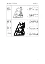
Страница 41: ... compressor has e heating tape it should also be removed Note When removing the power cable please mark the power cable color and corresponding terminal thus to avoid error during reinstallation 2 Remove the nuts fixing the compressor z Screw off the screws fixing the compressor with shifting spanner or box spanner z The removed screws should be put together in case of lost 3 Disconnect the pipe t...

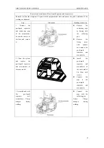
Страница 42: ... screws unitl it reach the steel bushing 5 Connect the suction and exhaust pipe of compressor to the system pipeline connect the power cord and check whether the compressor runs normally z Connect the suction and exhaust pipe to the compressor and weld it Nitrogen must be charged when welding z After welding charge high pressure nitrogen to test leak z Energize the unit and crawl the AC contactor ...

Страница 43: ...ve the 4 way valve 2 Clean the system replace the 4 way valve of the same model The piping should be the same as it is before removal z the new 4 way valve should be the same as the replaced one If not it should be confirmed by the professionals z wrap the the 4 way valve with wet cloth z Connect the the 4 way valve with the four connecting pipe according to the original direction z Connect the pi...

Страница 44: ... remove it z Remove the connecting pipe by heating with the soldering gun z Remove the fixing screw with spanner and remove the gas Liquid separator and accumulator 2 Clean the system and replace the gas Liquid separator and accumulator of the same model z Insatll the gas Liquid separator and accumulator of the same model Fix them with screws z Connect the pipe to the gas Liquid separator and accu...

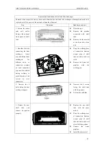
Страница 45: ... there may be different heat exchangers for different units so connection position of each connection pipe must be marked during welding to avoid blow by of the system by error connection z Wrap the welding place of connection between copper pipe of shell tube and tube with wet cloth z Remove the 4 pieces of pipeline with the welding gun 4 Unscrew the 4 bolts fixing the heat exchanger support z Un...

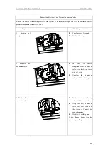
Страница 46: ... tube connecting condenser Pay attention to flame direction of welding gun to avoid burnout of condenser fin and sheet metal sub assy z Unsolder the connection pipe of condenser according to the left illustration 4 Remove the clamp fixing the joint and unsolder the two pieces of small pipe at the bottom of condenser z Remove the support fixing the joint with a spanner z Unsolder the samll connecti...

Страница 47: ...of refrigerant z Cut off power of the unit z Reclaim the refigerant 2 Remove the expansion valve z In order to ensure completeness of expansion valve wrap the 4 way valve with wet cloth z Unsolder the expansion valve with the welding gun 3 Replace the new expansion valve z Replace the new 4 way valve with the same model z Wrap the new expansion valve with wet cloth and then install it Connect the ...

Страница 48: ...ruction 1 Reclaim the refrigerant z Cut off power of the unit z Reclaim the refrigerant 2 Remove the filter z In order to ensure completeness of filter wrap the filter with wet cloth z Unsolder the filter with the welding gun 3 Replace the new filter z Replace the new filter with the same model z Wrap the new filter with wet cloth and then install it Connect the connection pipe z Weld it with weld...

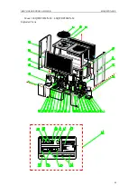
Страница 49: ...AIR COOLED SCROLL CHILLER MAINTENANCE 46 4 EXPLODED VIEWS AND PART LIST 1 Model LSQWF65M N M LSQWF80M N M Exploded Views ...

Страница 50: ...tion Strainer 07210044 1 13 Sensor sub assy 39001108 1 14 Scram switch 45010010 1 15 Front Panel 01538078 2 16 Wind Grill 01378001 2 17 Pressure Protect Switch 46020003 1 18 Front Panel 01538068 1 19 Fan Mesh Encloser 01478002 1 20 Fan Motor 15018003 1 21 Centrifugal Fan 10358001 1 22 Condenser Assy 0110801701 2 23 Front Panel 01538070 2 24 Terminal Board 22 Bit 42010249 2 25 Thermal Overload Rela...

Страница 51: ...ction Strainer 07210044 1 13 Sensor sub assy 39001108 1 14 Scram switch 45010010 1 15 Front Panel 01538078 2 16 Wind Grill 01378001 2 17 Pressure Protect Switch 46020003 1 18 Front Panel 01538068 2 19 Fan Mesh Encloser 01478002 1 20 Fan Motor 15018003 1 21 Centrifugal Fan 10358001 1 22 Condenser Assy 0110801501 2 23 Front Panel 01538070 2 24 Terminal Board 22 Bit 42010249 2 25 Thermal Overload Rel...

Страница 52: ...AIR COOLED SCROLL CHILLER MAINTENANCE 49 Model LSQWRF65M N M LSQWRF80M N M Exploded Views ...

Страница 53: ...1103 1 17 Thermal Expansion Valve 07130368 1 18 Pressure Protect Switch 460200044 1 19 Pressure Protect Switch 46020007 1 20 Scram switch 45010010 1 21 Front Panel 01538078 2 22 Compressor and fittings 00201108 1 23 One way Valve 07130111 1 24 Pressure Protect Switch 46020003 1 25 Condenser Assy 011080671 2 26 Front Panel 01308044 1 27 Wind Grill 01378001 2 28 Fan Motor 15018003 1 29 Centrifugal F...

Страница 54: ...03 14 Accumulator 2 07421108 15 Bidirection Strainer 1 07210044 16 Thermal Expansion Valve 1 07130354 17 Thermal Expansion Valve 1 07130327 18 Pressure Protect Switch 1 460200044 19 Pressure Protect Switch 1 46020007 20 Scram switch 1 45010010 21 Front Panel 2 01538078 22 Compressor and fittings 1 00201109 23 One way Valve 1 07138042 24 Pressure Protect Switch 1 46020003 25 Condenser Assy 2 011080...

Страница 55: ...CE 52 39 AC Contactor 2 4401023501 40 Single phase Air Switch 1 45020203 41 Phase Reverse Protector 1 46020054 42 Transformer 1 4311024001 43 Main Board 1 30222603 44 Electric Cabinet Assy 1 01391114 3 Model LSQWF130M N M Exploded Views ...

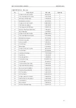
Страница 56: ...tect Switch high 46020003 1 14 Gas Tube Filter 07219051 1 15 Scram switch 45010010 1 16 Front Panel left 01538007 2 17 Condenser Assy 0112112302 2 18 Fan Mesh Encloser 01478003 1 19 Fan Motor 15018002 1 20 Centrifugal Fan 10358002 1 21 Front Panel right 01538009 2 22 Wind Grill 01368007 4 23 Front Panel down 1 01538013 2 24 Thermodynamic Expansion Valve right 07130343 1 25 Terminal Board 22 Bit 42...

Страница 57: ...AIR COOLED SCROLL CHILLER MAINTENANCE 54 36 Electric Cabinet Sub Assy 01391150 1 4 Model LSQWRF130M N M Exploded Views ...

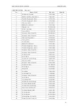
Страница 58: ...al Expansion Valve 07130343 2 15 Gas Tube Filter 07219051 2 16 Sensor sub assy 39001103 1 17 Scram switch 45010010 1 18 Front Panel left 01538007 2 19 Condenser Assy 0110807001 2 20 Fan Mesh Encloser 01478003 1 21 Fan Motor 15018002 1 22 Centrifugal Fan 10358002 1 23 Front Panel right 01538009 2 24 Wind Grill 01368007 4 25 Terminal Board 22 Bit 42010249 2 26 Thermal Overload Relay 44020356 4 27 Te...

Отзывы: