background image

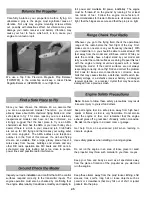
Carefully balance your propellers before flying An
unbalanced prop is the single most significant cause of
vibration Not only may engine mounting screws vibrate
out, possibly with disastrous effect, but vibration may also

damage your radio receiver and battery Vibration may
cause your fuel to foam, which will, in turn, cause your

engine to run lean or quit.

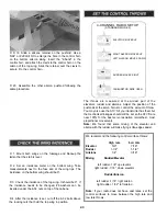
full power and maintains full power, indefinitely The engine
must be "broken-in" on the ground by running it for at least

two tanks of fuel Follow the engine manufacturer's

recommendations for break-in Make sure all screws remain

tight, that the hinges are secure and that the prop is on tight

We use a Top Flite Precision Magnetic Prop Balancer

(TOPQ5700) in the workshop and keep a Great Planes
Fingertip Balancer (GPMQ5000) in our flight box.

Whenever you go to the flying field, check the operational
range of the radio before the first flight of the day First,
make sure no one else is on your frequency (channel) With
your transmitter on, you should be able to walk at least 100

feet away from the model and still have control While you
work the controls, have a helper stand by your model and
tell you what the control surfaces are doing Repeat this test
with the engine running at various speeds with a helper
holding the model If the control surfaces are not always
responding correctly, do not fly! Find and correct the problem
first Look for loose servo connections or corrosion, loose
bolts that may cause vibration, a defective on/off switch, low
battery voltage or a defective receiver battery, a damaged
receiver antenna, or a receiver crystal that may have been

damaged from a previous crash.

Since you have chosen the Ultimate 40, we assume that
you are an experienced modeler Therefore, you should
already know about AMA chartered flying fields and other

safe places to fly If for some reason you are a relatively
inexperienced modeler and have not been informed, we
strongly suggest that the best place to fly is an AMA
chartered club field Ask the AMA or your local hobby shop
dealer if there is a club in your area and join Club fields
are set up for R/C flying and that makes your outing safer
and more enjoyable The AMA address and telephone
number is in the front of this manual If a club and flying
site are not available, find a large, grassy area at least 6
miles away from houses, buildings and streets and any
other R/C radio operation like R/C boats and R/C cars. A
schoolyard may look inviting but is too close to people,

power lines and possible radio interference.

Note: Failure to follow these safety precautions may result
in severe injury to yourself and others.

Keep all engine fuel in a safe place, away from high heat,
sparks or flames, as fuel is very flammable Do not smoke
near the engine or fuel, and remember that the engine

exhaust gives off a great deal of deadly carbon monoxide.
Do not run the engine in a closed room or garage.

Get help from an experienced pilot when learning to
operate engines.

Use safety glasses when starting or running engines.

Do not run the engine in an area of loose gravel or sand;

the propeller may throw such material in your face or eyes

Keep your face and body as well as all spectators away

from the plane of rotation of the propeller as you start and

run the engine.

Inspect your radio installation and confirm that all the control

surfaces respond correctly to the transmitter inputs The
engine operation must also be checked by confirming that
the engine idles reliably, transitions smoothly and rapidly to

Keep these items away from the prop' loose clothing, shirt
sleeves, ties, scarfs, long hair or loose objects such as
pencils or screwdrivers that may fall out of shirt or jacket
pockets into the prop.

45

Содержание Ultimate 40

Страница 1: ...he use by the user of the final user assembled product By the act of using the user assembled product the user accepts all resulting liability If the buyer is not prepared to accept the liability asso...

Страница 2: ...e 37 Suggested Covering Sequence 38 Painting 38 Final Hookups and Checks 38 Install the Hinges 38 Install the Hardware 39 Attach the Canopy 39 Radio Installation 40 Install the Rudder Elevator and Thr...

Страница 3: ...g 3 Use an R C radio system that is in first class condition and a correctly sized engine and components fuel tank wheels etc throughout your building process 4 You must properly install all R C and o...

Страница 4: ...balsa filler such as Hobbico HobbyLite Hobbico HCAR3400 D 1 4 20 Tap and Drill GPMR8105 D IsopropyI rubbing alcohol 70 D White body putty Squadron SQUR1500 D Ballpoint pen D 90 Building square HCAR048...

Страница 5: ...h the plan and the parts list included with this kit Using a felt tip or ballpoint pen lightly write the part name or size on each piece to avoid confusion later Use the die cut patterns shown on page...

Страница 6: ...6...

Страница 7: ...7...

Страница 8: ...as a guide to make sure the stab TE is straight as you glue it in position Note Refrain from using excessive accelerator Hours after it s sprayed on residual accelerator can prematurely and unexpected...

Страница 9: ...e plans or a straightedge as a guide to make sure the rudder LE is straight as you glue it in position D 1 Pin the die cut 1 4 balsa fin bottom S 2 over the fin plan Cut the fin outer frame from a 1 4...

Страница 10: ...flat surface Mark a test line on the trailing edge of the stab B Flip the stab over and mark another line in the same location as the first If you see only one line then it is on center Proceed and m...

Страница 11: ...cess deep enough for the torque rod D 2 Drill 3 32 pilot hole into the elevator LE on the centerline at the torque rod marks As you drill the holes keep the drill aligned with the top and bottom surfa...

Страница 12: ...th a hobby knife as shown in the sketch above TWO WARPED SPARS INSTALLED THIS WAY WILL RESULT IN A WARPED WING D 2 Match sets of 1 4 x 3 8 x 24 balsa wing spars so any warps will counteract each other...

Страница 13: ...in spar and the joiner ends should be flush with the forward edge of the main spar Make sure the top of the joiner is flush with the bottom of the slots for the top main spar D 12 Use 6 minute epoxy t...

Страница 14: ...ge of the sheet should cover the forward half of the main spar The root end should cover one R 4 and R 5 rib D 17 From a 1 16 x 3 x 24 balsa sheet cut and glue shear webs perpendicular to the aft edge...

Страница 15: ...g flush with the side of tip rib R 1 D 8 Use a 1 16 x 3 x 30 balsa sheet to make the center sheeting between the LE sheet and the TE sheet Save the remaining sheeting for the bottom center sheeting Th...

Страница 16: ...sheeting flush with the side of tip rib R 1 D 8 Make the wing tips from a 1 8 x 3 x 18 balsa sheet Hold the sheet against tip rib R 1 and draw an outline of the rib Cut and glue the wing tips to tip r...

Страница 17: ...ervo tray perpendicular to the tray Glue the tray doublers to the bottom of the aileron servo tray D 10 Glue the servo tray to ribs R 6 D D 1 Trim one end of the 1 1 4 x 24 balsa aileron to the same a...

Страница 18: ...red drill 5 32 holes at the four engine mount punch marks Drill a 3 16 hole for the throttle pushrod at the appropriate location Drill two 1 4 fuel line holes in the center of the engine mount holes D...

Страница 19: ...Drill 5 16 holes at the punch marks on the upper fuse sides D 3 Caution Make sure to glue the right side doublers to the right side fuse Position the fuse sides next to each other as shown Glue the d...

Страница 20: ...e formers perpendicular to your building board use thin CA to glue formers F 12 thru F 8A B to the fuse sides top deck and aft fuse bottom The fuse sides should be perpendicular to the building board...

Страница 21: ...r plate Insert 6 32 x 1 2 cap head screws with 6 washers through the landing gear and landing gear plate Thread a 6 32 blind nut on the cap head screw from the back side of the landing gear plate Scre...

Страница 22: ...mer F 11 and cross each other before passing through former F 10 Approximately 7 of the guide tube should protrude past F 10 D 1 With the fuselage upside down in a foam cradle fit the wing in the wing...

Страница 23: ...nd the high side of the stab plate until the stab is aligned Check that the stab tips measure the same distance from the center of the firewall Draw alignment marks on the bottom of the stab Remove th...

Страница 24: ...p of the fuse and stab Next glue it to the formers and backrest Finally glue it to the stringers and the fin D 6 Repeat the process to install the turtledeck sheet on the other side of the fuselage D...

Страница 25: ...and former F 5 The center lingitudinal brace is die cut as two pieces and will need to be glued together Glue the die cut 1 8 balsa former F 6 over the longitudinal braces D 11 Remove the elevator joi...

Страница 26: ...die cut 1 8 plywood tank hatch lip on top of the offset flush with the front of the off set D 7 Make two 13 1 2 long top deck sheets from the 3 32 x 3 x 36 balsa sheet Fit the edge of one sheet agains...

Страница 27: ...the die cut 1 8 plywood ribs R 10 and R 11 sandwiched between ribs R 8 Glue the die cut 1 8 ribs R 12 and R 13 sandwiched between the ribs R 9 D 1 Pin the die cut 3 32 balsa ribs R 1 and R 7 in posit...

Страница 28: ...with the bottom of the slots for the top main spar Allow the epoxy to cure before proceeding with the next step D 10 Trim the leftover LE to fit between the installed LE When satisfied with the fit gl...

Страница 29: ...hine screw from the bottom up through the top of the forward cabane and a 6 32 x 1 1 2 machine screw in the aft cabane Secure the screws to the cabane with 6 32 nuts D 22 Use masking tape to hold the...

Страница 30: ...d should cover to the center of rib R 10 D 1 Mount the top wing on the fuse along with the struts D 3 Position the front of the LE sheet against the LE and glue it in position with thin CA D 4 Careful...

Страница 31: ...f the cap strip on the R 1 tip rib should be flush with the side of the rib On the double rib for the strut glue tow cap strips D 5 Drill a 5 32 hole through the top center sheeting using the hole thr...

Страница 32: ...use and at the wing tips If the distance at the tips is larger reduce the length of the struts a little at a time until the wings are parallel D 1 Sand the TE sheet and TE flush D 2 Mark the centerlin...

Страница 33: ...g Cut the hinge slots and without using glue test fit the aileron to the wing D D 6 Remove the aileron from the wing Mark the bevel to lines and trim the LE of the aileron to a V as shown on the plan...

Страница 34: ...em together the seam will be as small and straight as possible Notice that the rear of the pant halves do not overlap Roughen all the areas that are to be glued including the indentation on the inside...

Страница 35: ...ely 1 8 D 11 Enlarge the axle notch to 11 64 in the landing gear Temporarily mount the wheel pant to the landing gear with another 8 32 nut Note When you reinstall the wheel after the wheel pant has b...

Страница 36: ...d remove the tape and make sure you have thoroughly glued the two pieces together by inspecting the glue joints and adding thin CA if necessary D 6 Drill a 3 32 hole through the cowl and fuse at each...

Страница 37: ...from the model with compressed air or a vacuum with a brush and a tack cloth Do not confuse this procedure with checking the C G that will be discussed later in the manual Now that the model is nearl...

Страница 38: ...f the canopy that is not to be painted If you are not sure that the paint is compatible with the clear canopy test the paint on a leftover piece of canopy material For painting the pilot we have disco...

Страница 39: ...Install the rudder with its hinges Repeat the gluing technique described previously and allow the epoxy to cure D 1 Assemble the fuel tank according to the manufacturer s instructions Remove the fuel...

Страница 40: ...the servo tray with the servos aft D 4 Plug the servos into the receiver Wrap the receiver in foam padding and rubber band it in the servo tray Insert the servo tray under the outer pushrod tubes and...

Страница 41: ...e control horns With the radio switched on and the servos centered position the control surfaces to neutral Mark the pushrod where it crosses the mounting holes in the servo arm D 11 Install a silicon...

Страница 42: ...aslinks as described before D D 15 Attach both wings to the fuse Position the small control horns on the TE of the ailerons in line with the struts With the control horn base flush with the TE of the...

Страница 43: ...n smoothest most proportional movement Note We found that some mixing of the elevator and aileron with the rudder will make flying knife edges easier D 1 Mount both wings on the fuselage and block up...

Страница 44: ...ops it is nose heavy and you must add weight to the tail to balance the model If possible first attempt to balance the model by changing the position of the receiver battery If you are unable to obtai...

Страница 45: ...eady know about AMA chartered flying fields and other safe places to fly If for some reason you are a relatively inexperienced modeler and have not been informed we strongly suggest that the best plac...

Страница 46: ...ve right of way to and avoid flying in the proximity of full scale aircraft Where necessary an observer shall be used to supervise flying to avoid having models fly in the proximity of full scale airc...

Страница 47: ...little slower and allow yourself time to think and react Add and practice one maneuver at a time learning how the Ultimate 40 behaves in each For smooth flying and normal maneuvers use the low rate s...

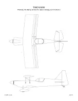
Страница 48: ...TWOVIEW Photocopy this drawing and use the copies to design your trim scheme PRINTED IN USA 3005155...

Отзывы: