


GPMA1425 Mnl
I N S T R U C T I O N M A N U A L
READ THROUGH THIS MANUAL BEFORE STARTING CONSTRUCTION. IT CONTAINS IMPORTANT
INSTRUCTIONS AND WARNINGS CONCERNING THE ASSEMBLY AND USE OF THIS MODEL.
WARRANTY
Great Planes
®
Model Manufacturing Co.
guarantees this kit to
be free from defects in both material and workmanship at the
date of purchase. This warranty does not cover any component
parts damaged by use or modification.
In no case shall Great
Planes’ liability exceed the original cost of the purchased kit.
Further, Great Planes reserves the right to change or modify this
warranty without notice.
In that Great Planes has no control over the final assembly or
material used for final assembly, no liability shall be assumed nor
accepted for any damage resulting from the use by the user of
the final user-assembled product. By the act of using the
user-assembled product, the user accepts all resulting liability.
If the buyer is not prepared to accept the liability associated
with the use of this product, the buyer is advised to return
this kit immediately in new and unused condition to the
place of purchase.
To make a warranty claim send the defective part or item to
Hobby Services at the address below:
Hobby Services
3002 N. Apollo Dr. Suite 1
Champaign IL 61822 USA
Include a letter stating your name, return shipping address, as
much contact information as possible (daytime telephone
number, fax number, e-mail address), a detailed description of
the problem and a photocopy of the purchase receipt. Upon
receipt of the package the problem will be evaluated as quickly
as possible.
Entire Contents © 2012 Hobbico,
®
Inc. All rights reserved.
Champaign, Illinois (217) 398-8970
email:
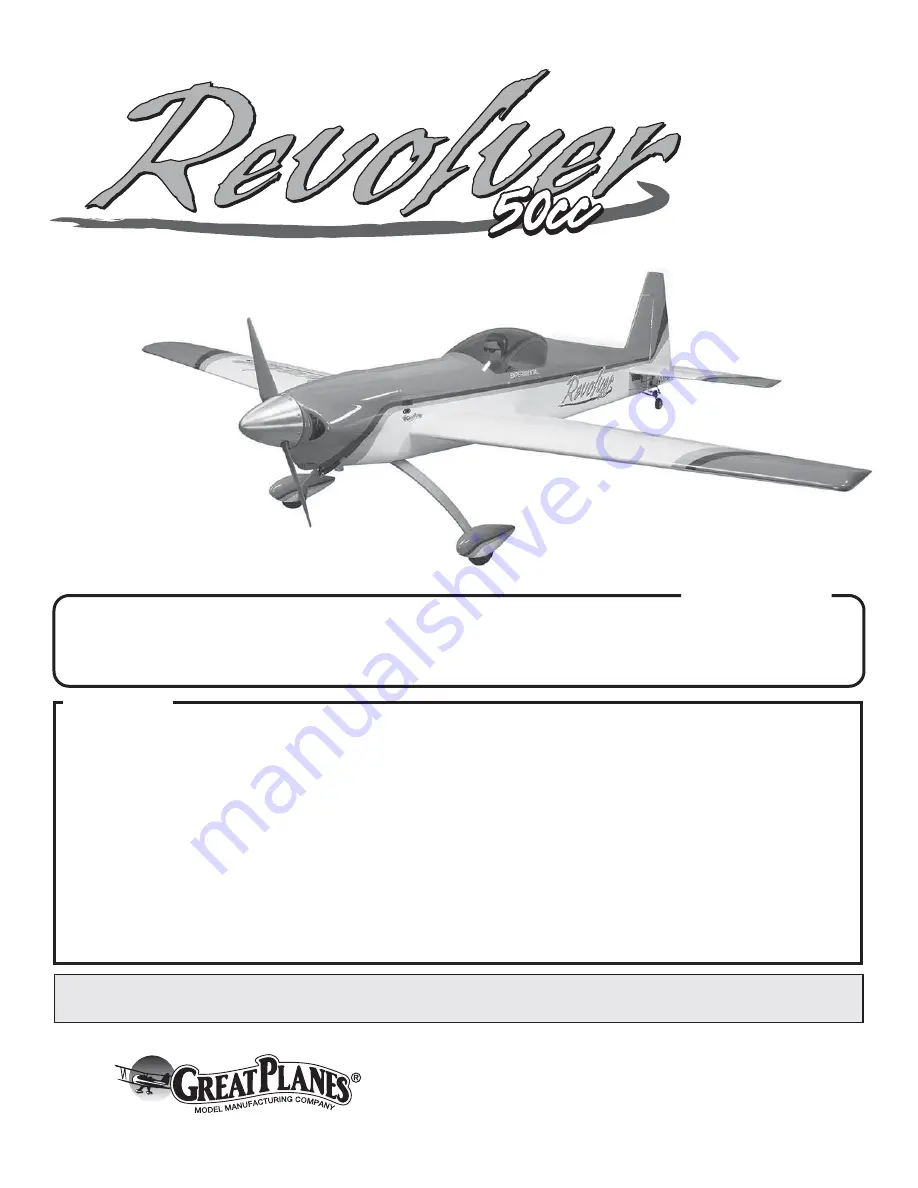
SPECIFICATIONS
Wingspan:
90 in [2285 mm]
Wing Area:
1303 in
2
[84 dm
2
]
Wing Loading:
34− 36 oz /ft
2
[104 −110 g /dm
2
]
Length:
82.5 in [ 2095 mm]
Weight:
19.5 − 20.5 lb [8840 − 9300 g]
Radio:
4 channel minimum
Engine:
50 cc two stroke
gasoline engine
Содержание Revolver 50cc
Страница 32: ...GPMA1425 Mnl...


