GREAT PLANES Matt Chapman Cap 580 Скачать руководство пользователя страница 17

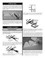
1. Cut the pilot to shorten it to fit into the cockpit. Glue it

in place.

2. Install the instrument panel decal to the front of the cockpit.

3. Trim the canopy on the molded cut lines. Glue the canopy

in place with RC 56 canopy glue or other aliphatic glue.

4. Install the propeller that is best suited to your engine

and the spinner included in the kit.

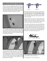
1. Use scissors or a sharp hobby knife to cut the decals from
the sheet.

2. Be certain the model is clean and free from oily
fingerprints and dust. Prepare a dishpan or small bucket with
a mixture of liquid dish soap and warm water—about one
teaspoon of soap per gallon of water. Submerse the decal in
the soap and water and peel off the paper backing. Note:
Even though the decals have a “sticky-back” and are not the
water transfer type, submersing them in soap & water allows
accurate positioning and reduces air bubbles underneath.

3. Position decal on the model where desired. Holding the
decal down, use a paper towel to wipe most of the water away.

4. Use a piece of soft balsa or something similar to
squeegee remaining water from under the decal. Apply the
rest of the decals the same way.

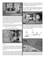
1. Turn on the transmitter and receiver and center the

trims. If necessary, remove the servo arms from the servos
and reposition them so they are centered. Reinstall the
screws that hold on the servo arms.

2. With the transmitter and receiver still on, check all the

control surfaces to see if they are centered. If necessary, adjust
the clevises on the pushrods to center the control surfaces.

3. Make certain that the control surfaces and the

carburetor respond in the correct direction as shown in the
diagram. If any of the controls respond in the wrong direction,
use the servo reversing in the transmitter to reverse the
servos connected to those controls. Be certain the control
surfaces have remained centered. Adjust if necessary.

Use a Great Planes AccuThrow (or a ruler) to accurately
measure and set the control throw of each control surface as
indicated in the chart that follows. If your radio does not have
dual rates, we recommend setting the throws at the low rate
setting. NOTE: The throws are measured at the widest part
of the elevators, rudder and ailerons.

Set the Control Throws

CARBURETOR WIDE OPEN

RUDDER MOVES RIGHT

LEFT AILERON MOVES DOWN

RIGHT AILERON MOVES UP

ELEVATOR MOVES UP

4-CHANNEL

TRANSMITTER

(STANDARD MODE 2)

4-CHANNEL RADIO SETUP

TRANSMITTER

4-CHANNEL

TRANSMITTER

4-CHANNEL

TRANSMITTER

4-CHANNEL

Check the Control Directions

GET THE MODEL READY TO FLY

Apply the Decals

Install the Pilot and Canopy

FINAL TOUCHES

17

Содержание Matt Chapman Cap 580

Страница 1: ...ediately in new and unused condition to the place of purchase To make a warranty claim send the defective part or item to Hobby Services at the address below Hobby Services 3002 N Apollo Dr Suite 1 Ch...

Страница 2: ...ft corner of the page We urge you to join the AMA Academy of Model Aeronautics and a local R C club The AMA is the governing body of model aviation and membership is required to fly at AMA clubs Thoug...

Страница 3: ...Remember Take your time and follow the instructions to end up with a well built model that is straight and true Four channel radio Four 54 oz in servos and one 30 oz in servo One 6 150mm servo extens...

Страница 4: ...udy photos in following steps to get another view of the same parts The CAP 580 is factory covered with Top Flite MonoKote film Should repairs ever be required MonoKote can be patched with additional...

Страница 5: ...ron 15 Right Wing with Aileron 16 Wing Joiners Kit Contents Photographed 5 32 x 1 1 4 Axles 2 Brass EZ Connector 2 4 40 Blind Nuts 4 6 32 Blind Nuts 4 8 32 Blind Nuts 4 Axle Nuts 2 1 4 20 Blind Nuts 2...

Страница 6: ...ices and shipping and handling charges will apply Illinois and Nevada residents will also be charged sales tax If ordering via fax include a Visa or MasterCard number and expiration date for payment M...

Страница 7: ...have one use a high speed rotary tool to drill the holes 2 Use a sharp 11 blade to cut a strip of covering from the hinge slots in the wing and aileron 3 Cut eight 3 4 x 1 19mm x 25mm hinges from the...

Страница 8: ...r the servo then install a servo arm pointing towards the wingtip 4 Position a large nylon control horn on the aileron positioning it as shown in the sketch and aligning it with the servo Mark the loc...

Страница 9: ...d measure the dihedral The distance from the top of the bench to the center of the wing as measured at the wing tip should be approximately 3 3 8 86mm Block the wing tip up while the glue hardens Note...

Страница 10: ...drill bit drill from the top of the wing through the wing bolt holes drilling through the wing bolt plate 6 Mount the wing to the fuselage with two 1 4 20 nylon wing bolts 1 Test fit the stab into the...

Страница 11: ...selage Make sure it is perpendicular to the stab 8 Locate the tail wheel wire assembly Insert the wire into the tail wheel bracket as shown 9 Bend the wire 90 degrees Once the wire is bent cut the wir...

Страница 12: ...k of the fuselage 2 Cut the landing gear axles to a length of 1 3 16 30mm 3 File a flat spot on the end of the axles A high speed rotary tool works well for this also 4 Install an aluminum spacer it l...

Страница 13: ...s 9 Place the tray into the fuselage The front tongue on the tray extends forward to hold the fuel tank in position Drill a 1 16 1 6mm hole through the holes on each side of the tray Then screw a 2 x...

Страница 14: ...install your servo 15 Install a brass screw lock connector and nylon retainer to the servo arm Slide it onto the pushrod wire center the servo and install the servo arm onto the servo Then install the...

Страница 15: ...e ailerons Mark the location for the screw holes Drill through the marks you made with a 1 16 1 6mm drill bit drilling through the elevator Secure the control horn to the aileron with two 2 56 x 5 8 1...

Страница 16: ...s wire 10 Be sure the elevator servo is centered Enlarge the first hole in the servo arm with a Hobbico Servo Horn Drill or a 48 or 5 64 2mm drill bit Center the elevators and align the wire pushrod w...

Страница 17: ...he trims If necessary remove the servo arms from the servos and reposition them so they are centered Reinstall the screws that hold on the servo arms 2 With the transmitter and receiver still on check...

Страница 18: ...manently hold it in place Over time fuel and exhaust residue may soften the adhesive and cause the weight to fall off Use 2 sheet metal screws RTV silicone or epoxy to permanently hold the weight in p...

Страница 19: ...ngine manufacturer s instructions to break in the engine After break in confirm that the engine idles reliably transitions smoothly and rapidly to full power and maintains full power indefinitely Afte...

Страница 20: ...y 400 feet within 3 miles of an airport without notifying the airport operator I will give right of way and avoid flying in the proximity of full scale aircraft Where necessary an observer shall be ut...

Страница 21: ...on the runway Hold up elevator to keep the tail wheel on the ground If necessary adjust the tail wheel so the model will roll straight down the runway If you need to calm your nerves before the maide...

Страница 22: ...another attempt When you re ready to make your landing flare and the model is a foot or so off the deck smoothly increase up elevator until it gently touches down Once the model is on the runway and h...

Страница 23: ...turing quality controls and tight tolerances in design and tooling give Power Point props true constant pitch throughout the entire blade diameter This combined with lower rotational mass provides gre...

Страница 24: ...____________ Where Purchased _________________________ Date Construction Started __________________ Date Construction Finished _________________ Finished Weight __________________________ Date of Firs...

Отзывы: