157
Programming example - fi xed-wing model
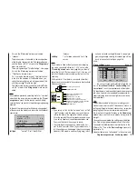
Programming example: servos running in parallel
In some cases a second servo is required to run in
parallel with an existing servo; for example, if a second
elevator or rudder is to be actuated by a separate servo,
or where a second servo is needed to cope with very
high control forces, or where two servos are required for
a large control surface due to the high forces involved.
This task could be solved simply by connecting both ser-
vos together in the model using a conventional Y-lead.
However, this has the drawback that the linked servos
cannot be adjusted individually from the transmitter, i. e.
you forfeit the basic advantage of the computer radio
control system: separate adjustment of individual servos
from the transmitter.
Another option would be to call up the Telemetry menu
and use its “Channel mapping” option instead of a
simple Y-lead; see page 121. However, the simplest
method is to use the transmitter’s software facilities. For
example, it is easy to set up …
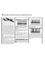
Two elevator servos
… to operate in parallel. First move to the …
“Basic settings”
menu
(page 56 … 62)
mod name
stick mode
motor at C1
1
idle re.
tail type
cut off
+150%
–100%
–––
2elev sv
… and set “2elev sv” in the “tail type” line.
The two elevator servos are then connected to receiver
output sockets 3 and 8.
Two rudder servos
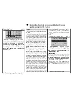
In this example we will connect two rudders “in parallel”
using the “
Free mixers
” menu. The second rudder could
be connected to receiver output 8, which is not already
in use.
The fi rst step is to move to the …
“Free mixers”
menu
(pages 107 … 111)
typ
fro
to
M1
M2
M3
??
??
rd
??
8
??
tr
… and set up a mixer “Tr RUD
¼
8”.
In the “Type” column select the “Tr” setting, so that the
rudder trim affects both rudder servos.
Finally switch to the graphics page and set a
SYM
metri-
cal mixer input of +100%:
MIX1
rd
8
tr v
0%
Offs
ASY
SYM
+100% +100%
tr
Once again, for safety reasons it is really essential that
you set input 8 to “free” in the “
Transmitter control
settings
” menu.
As an added refi nement, you may want both rudders
to defl ect outwards only, as part of a braking system
controlled by the Ch 1 stick. This can be accomplished
by setting up two additional mixers “
c1
¼
4
” and “
c1
¼
second rudder control channel
”, with suitable servo
travel settings. An offset of +100% is then selected for
both mixers, as the Ch 1 stick is (usually) at its top end-
point when the airbrakes are retracted, and the winglet
rudders are only required to defl ect outwards proportion-
ally when the brakes are extended.
Содержание mx-16 HOTT
Страница 1: ...Programming Manual 33116 mx 16 HoTT 2 gb H O P P I N G T E L E M E T R Y T R A N S M I S S I O N mx 16...
Страница 7: ...7 For your notes...
Страница 37: ...37 For your notes...
Страница 41: ...41 For your notes...
Страница 45: ...45 For your notes...
Страница 51: ...51 For your notes...
Страница 55: ...55 For your notes...
Страница 81: ...81 For your notes...
Страница 103: ...103 For your notes...
Страница 133: ...133 For your notes...
Страница 141: ...141 For your notes...
Страница 161: ...161 For your notes...
Страница 173: ...173 For your notes...


