background image

Operating the Menu System

Operator's Manual - LDK 5000

6-3

Systems Menu

The system functions of the camera are grouped into menus

and sub-menus. The systems menu is viewed in the viewfinder

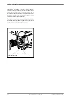
and navigated by means of the Rotary control and the Select

button which are both located at the front of the camera.

Entering the Systems menu

Press the Select button after the camera is switched on, the

message  Menu off appears in the viewfinder. Press the

Select button again while this text is showing, the MAIN menu

appears in the viewfinder.

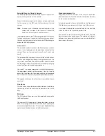
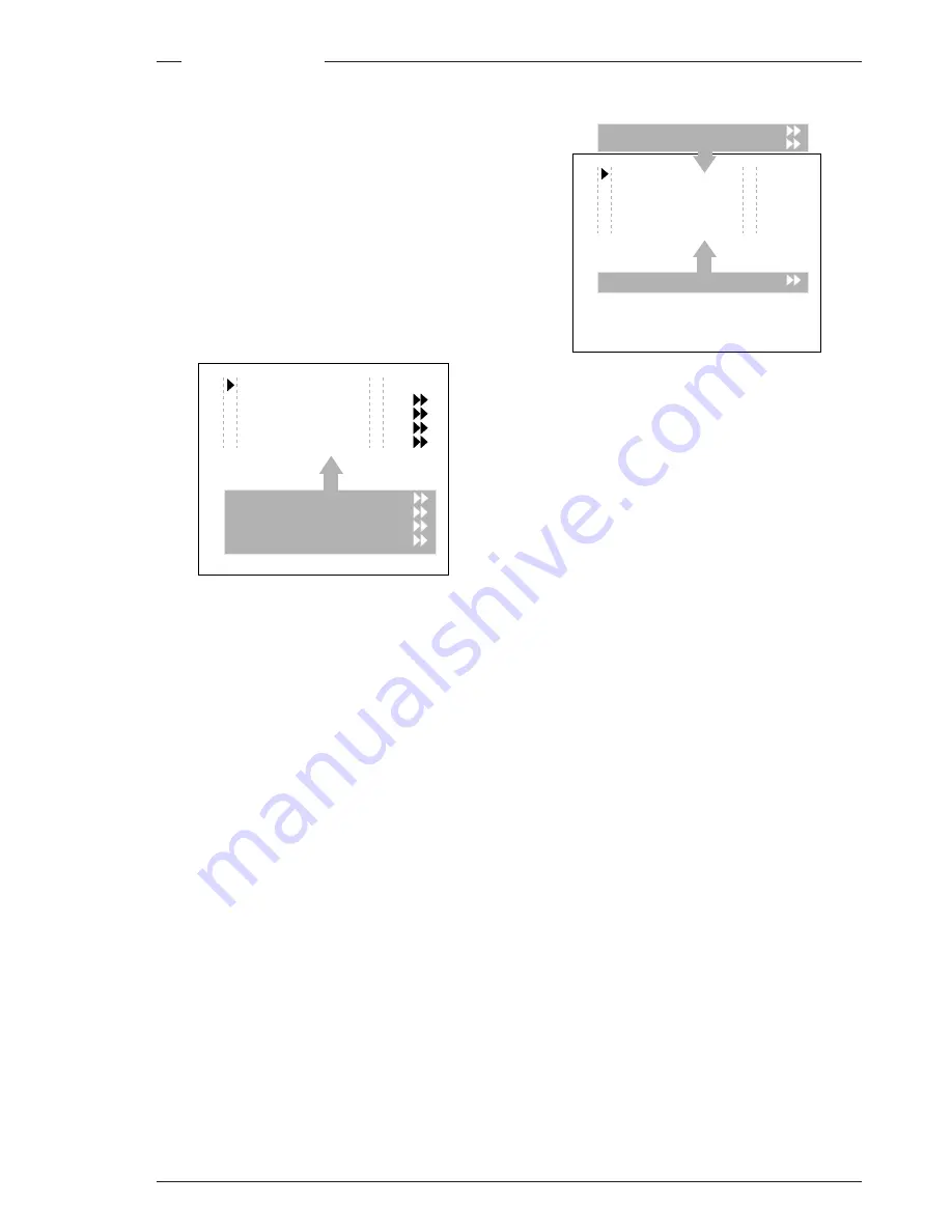
The MAIN menu screen shows five items. The name of the

menu is shown below these. Four more items are hidden but

become visible when you scroll down using the rotary control.

(Some of these items may not appear if the user level is not

set to 3.)

A cursor shows your position in the menu. The Rotary control

moves the cursor up and down.

Finding your way

Use the Rotary control to move the cursor through the menu

items. If a double arrow (>>) is visible, then pressing the

Select button brings you one level lower in the menu system.

Only five items are visible in each menu. Scroll up or down to

see any additional items.

When you first enter a menu (other than the MAIN menu) the

cursor is positioned next to the first item.

 The TOP and PREVIOUS entries are not immediately visible

but are located above the first item. Use the Rotary control to

scroll up to them.

-

Select TOP to bring you back to the MAIN menu.

-

Select PREVIOUS to go back to the menu that you were

in before the current one.

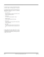
Menu off 

exec

VF 
Lens 
Video 
Install

Files
Security 
Diagnostics 
Service

MENU:   MAIN

The LENS menu above shows the items displayed when you

first enter the menu and the other items that are available by

scrolling up or down with the Rotary control.

Leaving the Systems Menu

If you are deep within the menu structure, follow these steps

to leave:

a. If necessary move the cursor to the leftmost column with

the Select button.

b. Scroll upwards with the Rotary control until the cursor

points to TOP (this is the MAIN menu).

c. Press the Select button. The cursor now points to the

Menu off item of the MAIN menu.

d. Press the Select button to leave the System menu.

This is the recommended way of leaving the System menu.

If you do not use the menu it disappears after a few seconds.

(This delay can be programmed in the VF menu.) However,

when you press the Select button again you enter the System

menu at the last position of the cursor and not at the top of

MAIN menu.

To prevent confusion the next time you enter the System

menu, it is advisable to leave the System menu by returning

to the MAIN menu (TOP) and selecting Menu off.

Lens type 

Std

Auto Iris 

On

Peak/Average 65
Auto iris setp. 

35

Mom. iris setp. 

50

Extended Iris

MENU:   LENS

TOP
PREVIOUS

Содержание LDK 5000

Страница 1: ... 6 Using the Menu System 6 1 Introduction 6 2 Systems Menu 6 3 Appendix A 1 System Menu Structure A 3 List of System Menu Functions A 14 List of Abbreviations A 16 About this Manual ii Introduction 1 1 Technology 1 2 Features 1 3 Smart Card 1 4 Important Precautions 1 5 Assembling the Units 2 1 Transport Case 2 2 Lens 2 3 2 inch Viewfinder 2 4 2 inch Viewfinder Accessories 2 5 Zoom Controls 2 6 Mi...

Страница 2: ...dix Section 1 Introduction This section outlines the technology used in the LDK 5000 camera and how this translates into a practical useable camera It lists the main features of the camera and also the precautions that must be taken into account when using it Section 2 Assembling the Units Section 2 provides information on the physical assembly of the camera and on how accessories can be used to e...

Страница 3: ...e LDK 5000 Triax camera and how this translates into a practical useable camera It lists the main features of the camera and also the precautions that must be taken into account when using it Section 1 Introduction Technology 1 2 Features 1 4 Contents Smart Card 1 5 Important Precautions 1 6 ...

Страница 4: ...highlights reproducing colours faithfully even overexposed skin tones Digital contrast circuitry provides a black stretch function for more detail in black areas and a black press function for improving the contrast impression by simulating the S curve of film SuperXPander The SuperXPander large lens adapter together with the optional 7 inch high resolution viewfinder turns the portable triax came...

Страница 5: ...e control around the white balance setting Smart card for personal settings and security Owner card for setting user levels and for copying and storing control settings Protected easy to operate controls and switches with read out of all settings Viewfinder status read out of primary camera functions Clean scan feature allows capture of computer and other monitor pictures Digital RS 232 interface ...

Страница 6: ... two different operator files to be stored on the card The recall and storage of a operator file is carried out via the Files menu of the menu system An operator file contains information relating to the set up of general camera preferences Note Only use an original camera card Store the owner card in a safe place Three smart cards are delivered with each camera These comprise of two user cards an...

Страница 7: ...lear Star 4P Star 6P Soft Focus 1 2 3 4 A B C D VTR Save Ext Iris Std File Smart card Power on P wel Tracker Aux Clear ND1 4 ND1 16 ND1 64 Clear Star 4P Star 6P Soft Focus 1 2 3 4 A B C D VTR Save Ext Iris Std File Smart card Power on P wel Tracker Aux Clear ND1 4 ND1 16 ND1 64 Clear Star 4P Star 6P Soft Focus 1 2 3 4 A B C D VTR Save Ext Iris Std File Smart card Power on P wel T Aux Avoid very da...

Страница 8: ...1 6 Operator s Manual LDK 5000 Introduction ...

Страница 9: ...sibilities of the camera The mounting of accessories and packing for transport are also explained Section 2 Assembling the Units Tripod Adapter Plate 2 8 SuperXPander 2 9 Shoulder Pad 2 10 Rain and Off use Cover 2 10 Script board 2 11 Top Light 2 11 Contents Transport Case 2 2 Lens 2 3 2 inch Viewfinder 2 4 2 inch Viewfinder Accessories 2 5 Zoom Controls 2 6 Microphone 2 7 ...

Страница 10: ...The camera is packed in the transport case as shown in the figure above This ensures that the camera is not damaged during transport Turn the 2 inch viewfinder downwards so that it does not protrude above the top of the camera Several foam packing inserts are provided to enable different configurations of the camera to be packed securely These inserts are used to support the rear of the camera Mak...

Страница 11: ...t the right side of the camera f Place the lens cable into the bottom clip at the front of the camera and clip 5 located at the side Pull and twist clip 5 to open it CAUTION Do not attach a lens weighting more than 5 kg to the camera without a support When a new lens is fitted to the camera it may be necessary to carry out some adjustments to optimize its use for example back focus or shading For ...

Страница 12: ...the optional eye piece cover 3922 405 00461 to the rubber eyepiece 3 Positioning the 2 inch viewfinder The horizontal position of the viewfinder can be adjusted as follows to suit your requirements a Loosen the locking ring 1 As seen from the rear of the camera turning the locking ring counterclockwise moves it towards the handle b Slide the viewfinder horizontally along the rail to the desired po...

Страница 13: ...low the eyepiece tube and swing it free of the button clip 3 c Press the button 4 above the eyepiece tube and remove the eyepiece d Fit the wide angle eyepiece 1 to the two clips 3 ensuring that they both click into place Wide angle eyepiece A left eye adapter is optionally available LDK 5390 10 toallowtheviewfindertobeusedwiththelefteye Before mounting the viewfinder onto the camera attach the le...

Страница 14: ...lable versions for different types of lens are LDK 6113 16 for Angenieux LDK 6113 26 for Canon LDK 6113 36 for Fujinon This control unit not only controls the zoom but also has mini button controls for the VTR start stop function and the VTR Ret function These are located under the front of the carrying handle 2 The instructions for mounting the zoom control unit and the function of the controls a...

Страница 15: ...f the camera and into clip 4 at the side of the camera Pull and twist clip 4 to open it Other microphones with a diameter of 21mm can also be used however ensure that the phantom power and the sensitivity of the input that match that type of microphone are correctly selected in the camera systems menu Refer to Section 6 for more information on selecting the audio inputs and controlling the audio l...

Страница 16: ...ottom of the camera engages the stud 2 at the rear of the tripod adapter plate b Firmly push the camera forward until it clicks into place CAUTION Failure to attach the camera to the tripod adapter plate in the correct manner could result in an unsecured camera Ensure that the rear stud 2 is engaged and that the camera clicks into place To remove the camera from the tripod proceed as follows a Pre...

Страница 17: ...tions This adapter allows larger studio lenses and a 7 inch viewfinder to be used with the camera Additional facilities provided include a utility power outlet and a rear control panel Refer to the User s Guide of the SuperXpander for more information on mounting the camera and other units to the SuperXpander as well as information on the additional functions of the SuperXpander ...

Страница 18: ... being put into storage For more information on how to put on the cover refer to the User s Guide which is supplied with it Note When the camera is used with the LDK 4482 SuperXPander the LDK 6989 00 optional rain and off use cover is available Rain and Off use Cover Shoulder Pad To change the position the shoulder pad press and hold lever 1 The shoulder pad can now be moved backwards and forwards...

Страница 19: ...light does not use more than 3W of power The script light is switched on and off and the intensity is varied with the knob 3 at the rear of the Script board The retaining rings and clip 4 can be screwed onto the right or left side if required 2 3 4 1 Clear Clear A 1 Star 4P ND1 4 B 2 Star 6P ND 1 16 C 3 Soft focus ND 1 64 D 4 Top Light To mount a top light 1 onto the camera proceed as follows a Sc...

Страница 20: ...2 12 Operator s Manual LDK 5000 Assembling the Units ...

Страница 21: ...on location or in a studio environment Information is also provided on the main video and audio signal paths through the camera head Section 3 Configurations Contents LDK 5000 Configurations 3 2 Single camera triax mode 3 3 Multiple camera mode 3 4 Two wire Data Control Bus 3 6 Other Control Features 3 6 Intercom Routing 3 7 Audio 3 8 ...

Страница 22: ...07 Master Control Panel LDK 4628 Universal OCP Rotary Style LDK 4629 Universal OCP Joystick Style LDK 5440 Triax Adapter LDK 4634 PC Interface Package LDK Software LDK 4505 Base Station LDK 5000 Camera Head LDK 5000 Camera Head LDK 5031 Tripod Adapter AJ MC700 Microphone Kit LDK 5210 Smart Cards LDK 5201 LCP 100 Local Control Panel LDK 5200 IR Remote Control LDK 5020 Flightcase LDK 5302 2 HDTV VF ...

Страница 23: ...ercom signals from the Base Station to the camera When used in the Triax mode remote control of the camera is achieved by a remote control panel of the Series 9000 Control System This can be an operational control panel OCP connected to the Base Station The data communication between camera and Base Station is carried over the Triax cable LDK 5000 Triax Cable Maximum Length 1 000 m 3 300 ft with 1...

Страница 24: ...IR camera base station 0 mains Camera Processing Unit HS mkII Triax Cable Maximum Length 800 m 2 625 ft with 14 mm cable 1000 m 3281 ft with minor performance degradation Base Station LDK 4501 CPU LDK 4058 mkII Clear ND1 4 ND1 16 ND1 64 Clear Star 4P Star 6P Soft Focus 1 2 3 4 A B C D VTR Save Ext Iris Std File Smart card Po we r on P we l Tracker Aux Prod Prog Cam Floor Eng Camera Base Station Pr...

Страница 25: ... Multicore Cable 25 p Maximum Length 350 m 1 150 ft Note A maximum of 15 looped through standard camera systems in one chain can be handeld however in a multiple system the load of a LDK 23 HS mkII is twice the load of a standard camera This configuration is the multiple camera Triax mode The camera is connected to a CPU as in the single camera Triax mode The data bus is looped through from CPU to...

Страница 26: ...predictable control situations could arise otherwise The MCP is also connected to the data bus however it is not necessary to set an internal assignment number The camera or cameras to be controlled are selected on the MCP front panel itself when operating the unit Private Data A private data channel is also available between the camera and the Base station This is a two way serial channel operati...

Страница 27: ...rog Prog Cam Cam Floor Floor Eng Eng RAD RAD Camer Camer aBase BaseStation Tracker Tracker Headset Camera Headset Studio PROG PROD ENG BS Headset CAM CAM PROG PROD ENG Sidetone Tracker PROD ENG CAM Tracker Floor PROG PROD ENG Sidetone ENG Cam ENG Out Clear ND1 4 ND1 16 ND1 64 Clear Star 4P Star 6P Soft Focus 1 2 3 4 A B C D VTR Save Ext Iris Std File Smart card Pow er on P we l Tracker Aux Sideton...

Страница 28: ...sed to the multiplexer transmitter section of the camera which sends them to the Base station via the Triax cable The amplification factor of the audio microphone signals can be selected via the systems menu the Base station or the Master Control Panel Phantom power is available for the audio microphones The defaultvalueis 48V refertoSection4 Audio forinformation on changing this value Audio ...

Страница 29: ...ctors on the camera These are grouped according to their function so as to provide a quick reference guide to the operation of a particular aspect of the camera The controls and connectors are shown for both the camera head and the Triax adapter Section 4 Location of Controls and Functions Contents Power Supply 4 2 Security and Access 4 3 Video Output 4 3 Video Functions 4 4 Monitoring Functions 4...

Страница 30: ...when the camera is in the Triax mode maximum current 1 5A The socket also provides access to an internal tally switch When the camera is on air the contact of the internal relay is closed Circuit breaker button BREAKER If excessive current flows in the camera the circuit breaker trips and shuts off power to all the units If this happens check the units for faults and if necessary take corrective a...

Страница 31: ...it fits snugly There are two types of card an owner card and a user card Both cards store operator files and scene files The owner card can be used to change the user level of the camera The user level determines which set of controls and functions can be changed by the camera operator Refer to Section 6 for more information on the smart card A smart card is not required for normal operation of th...

Страница 32: ...or two seconds recalls the standard scene file video values These values do not take effect immediately if the camera is on air they take effect when the camera goes off air Refer to the Appendix for the default values of the factory defined standard scene file Refer to Section 6 to find out how to define and assign a standard customer scene file Black Stretch switch This switch when set to the On...

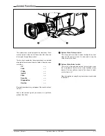
Страница 33: ...ailable when the camera is used in the stand allone mode and is not active when the camera is genlocked or on air VTR Start button In the triax mode this button switches the intercom microphone of the headset to the production intercom channel This button operates in parallel with the VTR button on the lens Gain selection switch This up down scroll selection switch gives a choice of five master ga...

Страница 34: ...external video signal from the Base Station is available at connector 2 External signal selection switch This switch selects either the EXT1 or EXT 2 signal for displayintheviewfinderwhentheviewfindersignalselection switch 6 is in the EXT position 1 2 5 6 4 3 1 2 3 4 5 6 Viewfinder selection switch This switch is used to select the camera Y signal or an external signal set with 6 for display in th...

Страница 35: ... Reduce the crispening for a better picture when the gain is set to Tally switch The tally switch is used to control the tally indicator at the front of the viewfinder When this switch is set to the ON position the tally indicator light when the camera is on air When this switch is set to the OFF position the tally indicator does not light when the camera is on air The tally swith does not control...

Страница 36: ...s is the minimum area seen on a TV set Non standard indicator The non standard video settings indicator lights when exposure is not set to nominal It also lights when black stretch or extended iris is on and if AWC or FL is selected with the Colour Temperature selector White Balance indicators The white balance indicators light as follows 3 2 preset temperature of 3200K is selected 4 7 preset temp...

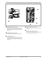
Страница 37: ...The gain of this audio channel can also be controlled Audio microphone connector rear Balanced input connector for a high quality microphone Audio microphone switch A 3 position switch that selects the audio microphone connector at the front or the connector at the rear The third position selects the rear connector with a phantom power supply 48V Audio microphone 2 connector rear Balanced input co...

Страница 38: ...l This control varies the volume of the production intercom signaltothecameraoperator sheadsetwhentheselection switch 2 is in the FRONT position Intercom routing switch A3 positionswitchthatroutesthecameraoperatorintercom microphone signal to engineering ENG or production PROD or turns off the intercom The momentary VTR switch at the front of the camera or on the lens can be used to route the came...

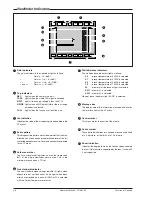
Страница 39: ...all Files Security Diagnostics Service Some of these items may not appear if the user level is not set to 3 Each of these menus gives you access to a particular group of functions System Menu Rotary control This rotary control is used to move through the various menus of the control system It is also used to vary the value of some functions System Menu Select switch This switch when pressed select...

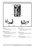
Страница 40: ...tion 0 25A The optional script board LDK 6985 15 is connected to this socket Teleprompter output socket This BNC conector supplies the 1Vpp teleprompter signal applied to the base station Auxilary Functions 1 2 3 4 5 6 Aux connector This 11 pole female socket provides analogue control signals and facilities for the connection of a private data channel see installation manual Tracker connector This...

Страница 41: ...hooting Screens 5 5 Exposure Time 5 6 This section contains information on the practical use of the camera using the viewfinder display and the switches at the front to control the camera Section 5 Shooting Contents Using the Camera 5 2 Colour Bar 5 3 Gain selection 5 3 Optical filter selection 5 3 ...

Страница 42: ...e and the viewfinder text display This section describes the operational functions that are available when using the camera via the viewfinder display and the switches at the front These offer a convenient way of accessing the menu system which provides full control of the camera There are a number of steps that must be carried out before satisfactory shots can be obtained a The camera must be set...

Страница 43: ...ing on the colour bar test signal The colour bar is a standard test signal which is used to set up and check the camera before use When the colour bar is selected the following functions are temporarily set to the values listed below Black stretch Off White limiter Off Zebra Off Safe area VF Off Cadre VF Off Gain selection Depending on the available light levels it may be necessary to adjust the g...

Страница 44: ...lue and the actual measured colour temperature The range of the auto white balance is from 2 5K to 20K In the auto white positions an electronic colour filter can be adjusted in the system Video menu This varies the colour balance to obtain warmer or colder colour effects When an automatic white balance process is performed the electronic colour filter is reset to its default value Auto White Bala...

Страница 45: ...onds to switch off the Clean Scan function Exposure Time returns to its previous non variable setting The ranges are from 50 6 to 125 for 50Hz video mode from 60 8 to 150 for 60Hz video mode from 24 4 to 96 for 25Hz or less video mode V SHIFT The vertical shift switch V SHIFT at the front of the camera is usedfordisplayswiththesameframefrequencyasthecamera for example TV sets It is an up down type...

Страница 46: ...er to objects in sharp focus The exposure time values of 1 200 1 500 and 1 1000 of a second are used to capture fast moving objects so that these can be played back sharply in slow motion The value selected depends on the speed of the moving object Note Increasing the exposure speed lowers the camera sensitivityproportionally Theexposureselectionalsoincludes lighting control positions whichcanbeus...

Страница 47: ...on describes the structure of the control system It contains procedures for controlling the menu system and explains how to program the menu system for your personal preferences The menu structure and the methods of function selection are also explained Section 6 Using the Menu System Contents Introduction 6 2 Systems Menu 6 3 ...

Страница 48: ...the large number of set up options it may require some time for you to become familiar with them all We recommend that you spend time using the various controls and displays in order to discover the wide range of possibilities Read the instructions in this section carefully but also feel free to examine the various menus in detail In this way you will learn quickly to intuitively operate the camer...

Страница 49: ...es are not immediately visible but are located above the first item Use the Rotary control to scroll up to them Select TOP to bring you back to the MAIN menu Select PREVIOUS to go back to the menu that you were in before the current one Menu off exec VF Lens Video Install Files Security Diagnostics Service MENU MAIN The LENS menu above shows the items displayed when you first enter the menu and th...
Страница 50: ... have to go to change a function consult the appendix to discover under which menu group or sub group the function you want to change is located If the cursor points to an item and there are no double arrows to indicate a sub menu then the item pointed to has a value The value can be a toggle value only two values a list value more than two values an analogue value variable from 00 to 99 or unavai...

Страница 51: ...reduced User level 0 is a special protection level which locks most of the operational controls of the camera Use this level to ensure that a camera that has been set up is not tampered with Userlevel0isnotnormallyusedforoperationalpurposes The appendix indicates which functions are available at each user level Run Hours This sub menu allows the date and time to be set and allows the running time ...

Страница 52: ...Files menu enables the scene files to be stored and recalled using the store and recall entries of the menu system If the message NOK is displayed then the old values are restored If the camera is on air when a scene file is recalled then the recalled values do not become active until the camera goes off air Operator files The Files menu also allows the recall of the opererator file stored in the ...

Страница 53: ...Appendix LDK 5000 Camera Head Software Status 12 A 1 Appendix Contents System Menu Structure A 3 List of System Menu Functions A 15 List of Abbreviations A 17 ...

Страница 54: ...vailable with different user levels Values column All available choices are listed for a function Blocked if column Lists the conditions that block the function Default column The default column lists the values of the functions when a camera is delivered Files column The File column indicates where the value of the function is stored in the operator file or in the scene file or not at all The sec...

Страница 55: ...Main Menu Menu text User Values Default Blocked if File VF Lens Video Install Files Security Diagnostics Service 0 0 2 0 1 0 2 3 Appendix LDK 5000 Camera Head Software Status 02 Page 1 ...

Страница 56: ...Ind On Off Off SuperXPander oper Focus Ind On Off Off No SuperXPander oper Zoom Ind On Off Off oper Box downright Fltr Off Off oper Marker Off 16 9 15 9 14 9 Off oper Marker 4 3 On Off Off oper Marker Type Dot Shad Both Dot oper Ind White 0 99 70 oper Ind Black 0 99 30 oper Display On Time Time oper Menu Time 0 10 sec 10 Display On oper Info Time 0 20 sec 5 oper Rotary Speed 0 10 5 oper VF Notch O...

Страница 57: ...m Iris Setpoint 0 99 50 scene Manufacturer Fuj1 Fuj2 Can Other Fuj1 Extended iris GainSpeed 0 99 5 oper ExpTimeSpeed 0 99 4 oper Min iris F5 6 8 11 16 F16 0 oper Max iris F1 4 2 2 8 4 5 6 F2 0 oper Min exp time 1 100 1 200 1 500 1 500 oper Max Gain dB 0 15 steps of 3 15dB oper Autoiris const Iris gain 5 10 5 3 3 3 3 3 0 0 3 3 S 3 0 3 S Appendix LDK 5000 Camera Head Software Status 02 Page 3 ...

Страница 58: ... Skin Off or 1 2 View Off On Off Skin Off Skin Level 0 99 50 Skin Off scene more width1 Red 0 99 50 Skin 1 scene width1 Blue 0 99 50 Skin 1 scene color1 Red 0 99 50 Skin 1 scene color1 Blue 0 99 50 Skin 1 scene width2 Red 0 99 50 Skin 2 scene width2 Blue 0 99 50 Skin 2 scene color2 Red 0 99 50 Skin 2 scene color2 Blue 0 99 50 Skin 2 scene Flare Flare S Off On On scene Red S 0 99 10 Flare Off scene...

Страница 59: ...m scene Master 0 99 76 gamma Pre scene Red 0 99 76 gamma Pre scene Green 0 99 76 gamma Pre scene Blue 0 99 76 gamma Pre scene more Curve BBC04 BBC05 BBC06 ARD 6xARD CCIR RAI ARD scene Gamma Gamma Lin gamma scene Matrix Matrix EBU RAI BBC B W SKIN 1 1 CFL VAR1 VAR2 Skin scene R G 0 99 Matrix Var scene G R 0 99 Matrix Var scene R B 0 99 Matrix Var scene B R 0 99 Matrix Var scene G B 0 99 Matrix Var ...

Страница 60: ...ding Off H par red 0 99 0 Shading Off H par green 0 99 0 Shading Off H par blue 0 99 0 Shading Off V saw red 0 99 50 Shading Off V saw green 0 99 50 Shading Off V saw blue 0 99 50 Shading Off V par red 0 99 0 Shading Off V par green 0 99 0 Shading Off V par blue 0 99 0 Shading Off Saturation 0 99 50 S S S S S S S S S S S S S 2 Appendix LDK 5000 Camera Head Software Status 02 Page 6 ...

Страница 61: ...Off oper Track Source Side Eng Side oper Cam Mic To CH1 CH2 CH1 oper Audio Audio 1 Gain 22 28 34 40 46 52 58 64 64 oper Audio 1 HPF On Off Off oper Audio 2 Gain 22 28 34 40 46 52 58 64 64 oper Audio 2 HPF On Off Off oper Notch Off On Off oper Exposure Lighting 10 10 0 Exp 50 60Hz scene Clean Scan Cl Scan Mode Normal Extended Normal scene Value See section 5 Shooting Screens scene Units Hz mSec mSe...

Страница 62: ...nute 0 59 Set Date Year 0 99 Month 1 12 Day 1 31 0 PIN code no owner card no PIN Four digits 0000 9999 0000 Customer files no owner card no PIN Store cust Scene Exec Store cust Oper Exec Green Button no owner card no PIN Standard Factory Customer Factory Scene file On Off On Operator file On Off On 0 0 2 2 2 2 2 2 2 0 0 0 0 Appendix LDK 5000 Camera Head Software Status 02 Page 8 ...

Страница 63: ...ec Attributes File select available files File name Attribute R W R R W no card Standard files not installed Standard settings Exec Lighting Night Exec Fluorescent Exec Extreme contrast Exec Creative Sport warm colour Exec Sport interview Exec HI film Exec HI film skin Exec LO Film Exec LO film skin Exec Sepia film Exec Matching LDK9x LDK10 Exec DVW xxx Exec HL xxx Exec Standard settings Exec 2 2 ...

Страница 64: ...daptor Type Triax DVCPRO Sensor Type IT ITW FT DPM Sensor Voltage Ok NotOk Shutter Run Run Stop Front Power Ok NotOk Y carrier Ok NotOk Cam 12nc Cam Version Cam Status Cam Boot ver Cam FPGA ver Adapter 12nc Adapter Status PPG Status DVP Status 2 2 2 S 2 2 2 2 2 2 2 2 2 S 2 S S S Appendix LDK 5000 Camera Head Software Status 02 Page 10 ...

Страница 65: ... Chroma Off On On Calibrations Video ADC Off Run Off 3200K Off Run Off 3200K reset Cust Fact Fact Pulse comp Off Run Run Calib Params Tolerance 0 1 1 25 3 Scaler Encoder Off On Off SDI Off On Off Encoder Colourbar Off On Off EPLD Test Off Sawt Bars Off Chroma Off On On 3 0 3 3 S S S 0 2 S S S S 3 3 Appendix LDK 5000 Camera Head Software Status 02 Page 11 ...

Страница 66: ... Sensor Voltage Diagnostics Shading parameters Video Shading Shading switch Video Shading Shutter Run Diagnostics Shutter phase Service Standard files Files Standard Settings Files Standard Files Store Scene file Files Store oper file Files Software status Diagnostics Tally Light switch Install Tolerance Service Calib Params User level select Security Installed level VF 4 3 Area type VF Audio Bar ...

Страница 67: ...red lvl level man manual max maximum mic microphone min minute min minimum mom momentary mon monitor nam non additive mix nd neutral density ndf no drop frame ocam camera operator file ocard smart card operator file op operation oper operator outp output ovl overload pin personal indentification number r w read write re rear repl replay r run record run rst reset sawt sawtooth scam camera scene fi...

Страница 68: ...Appendix LDK 5000 Camera Head Software Status 02 A 17 ...

Отзывы: