GRASS VALLEY LDK 3000+ Скачать руководство пользователя страница 21

LDK 3000+ High-Definition Camera Head User’s Guide (v1.0)

21

Chapter 2 - Installation

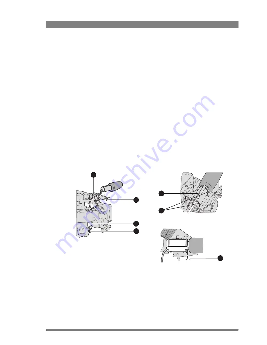
2.4  AJ-MC700 Microphone

To attach the optional microphone to the camera proceed as follows:

1.

Open the microphone holder by unscrewing the knurled screw (2) of the microphone 
support bracket (1) on the viewfinder and open.

2.

Slide the microphone into the split tube until the microphone shoulder reaches the mark 
(5) in the tube.

3.

Place the tube with the microphone into the holder with the split facing upwards. Mount 
the microphone as straight as possible.

4.

Ensure that the rubber supports at the back and front of the holder fit into the rims (6) 
around the tube.

5.

Close the holder and tighten the knurled screw at the top. Don’t allow the wind hood to 
touch the holder (7) as this reduces the damping effect.

6.

Connect the microphone cable to the 

MIC

 audio connector (3) on the right side of the 

camera. To avoid mechanical pick-up, do not let the microphone cable touch the holder.

7.

Place the microphone cable into the top clip at the front of the camera and into clip (4) at 
the side of the camera. (Pull and twist clip to open it.)

Other microphones with a diameter of 21 mm can also be used, however, ensure that the 
sensitivity of the input that match that type of microphone are correctly selected in the camera 

INSTALL

 menu. When a longer microphone is used, it is not necessary to place it in the split 

tube. Phantom power is always present on the front microphone socket.

2

4

1

3

5

7

6

Содержание LDK 3000+

Страница 1: ...3922 496 31881 October 2011 v1 0 LDK 3000 User s Guide High Definition Camera Head ...

Страница 2: ...environment Operation of this product in a residential area is likely to cause interference in which case the user at his own expense will be required to take whatever measures may be required to correct the interference Copyright Copyright Grass Valley Nederland B V 2011 Copying of this document and giving it to others and the use or communication of the contents thereof are forbidden without exp...

Страница 3: ... lens 17 2 2 LDK 5302 60 2 inch viewfinder 18 2 2 1 Mounting viewfinder and microphone holder 18 2 2 2 Positioning the viewfinder 19 2 3 2 inch viewfinder accessories 20 2 3 1 LDK 5390 00 Wide angle eyepiece 20 2 3 2 LDK 5390 10 Left eye adapter 20 2 4 AJ MC700 Microphone 21 2 5 LDK 5301 10 Tripod adapter plate 22 2 6 Adjusting the shoulder pad 23 2 7 Exchanging the camera adapter 24 2 8 LDK 5020 ...

Страница 4: ...g audio 44 4 6 4 Intercom 45 4 7 Managing files 46 4 7 1 Scene files 46 4 7 2 Operator files 46 4 7 3 Standard files 47 4 7 4 Customer standard files 47 4 8 Access and security 48 4 8 1 User level 48 4 8 2 Selecting the user level 48 4 8 3 Disable camera 48 4 8 4 Access control 48 Chapter 5 Video setup 5 1 Video acquisition modes 49 5 2 Video settings 50 5 2 1 Overview 50 5 2 2 Standard settings 5...

Страница 5: ...5 Video menu structure continued 70 6 2 6 Install menu structure 71 6 2 7 Files menu structure 72 6 2 8 Security menu structure 72 6 2 9 Diagnostics menu structure 73 6 2 10 Service menu structure 74 6 3 Menu contents 75 6 3 1 Viewfinder menu 75 6 3 2 Lens menu 77 6 3 3 Video menu 79 6 3 4 Install menu 84 6 3 5 Files menu 87 6 3 6 Security menu 88 6 3 7 Diagnostics menu 89 6 3 8 Service menu 91 Ch...

Страница 6: ... This program accepts any Grass Valley branded equipment Upon request a Certificate of Recycling or a Certificate of Destruction depending on the ultimate disposition of the product can be sent to the requester Grass Valley will be responsible for all costs associated with recycling and disposal including freight however you are responsible for the removal of the equipment from your facility and p...

Страница 7: ...d against any unintended operation The appropriate servicing authority must then be informed For example safety is likely to be impaired if the apparatus fails to perform the intended function or shows visible damage Any changes or modifications not expressly approved in this manual could void your authority to operate this equipment Cautions and Warnings Read and comply with the warning and cauti...

Страница 8: ... safety reasons To avoid electrical shock do not remove covers or panels Refer servicing to qualified personnel only In case of an emergency ensure that the power is disconnected Connect the product only to a power source with the specified voltage rating To prevent risk of overheating ventilate the camera correctly Do not block the hot airflow coming from the outlets on the right side of the came...

Страница 9: ...n direct sunlight or close to heating appliances for extended periods Do not allow sunlight to shine into the viewfinder Do not allow laser beams to shine into the lens as this could damage the imagers Avoid extreme highlights as these can cause various kinds of optical reflections Be careful when connecting and disconnecting Triax cables Do not mix units from different types of camera systems HD ...

Страница 10: ...nts can result in damage to the equipment For example a monitor connected directly to the CVBS output of the camera is powered locally The earthing point of the monitor s power supply can be at a different potential with respect to the earthing point of the Base Station If the power earth of the monitor is also the video earth then this earth potential is transferred to the camera via the shield o...

Страница 11: ... information necessary to use the camera in different configurations and with various attachments This manual describes all operating features of the camera so it can be used to its full potential This guide is so designed that it can be used as an introduction to those who are new to the camera as a simple procedural guide to those who wish to set up and start shooting immediately and as a refere...

Страница 12: ...s This means that continuous automatic correction is applied without operator intervention To make images look their best the LDK 3000 contains powerful colorimetry and color matching capabilities It also contains two independent skin detail circuits These circuits allow you to select any two color values and adjust detail processing in those areas thus allowing improvement in the appearance of fa...

Страница 13: ...ques minimize cross talk and interference Teleprompter and viewfinder signals maintain high performance with relatively long cable lengths The communication facilities provide for two wire or four wire high quality intercom signals Full camera control is provided via a C2IP Ethernet based control network The LDK 5630 TriaxHD adapter is equipped with a rotary Triax connector which provides freedom ...

Страница 14: ...ss solution CLASS compatible with many digital lenses User definable noise reduction Digital gamma with unique standard preset values and highest accuracy Digital detail with an extensive range of parameters Advanced detail correction includes two automatic skin settings Intelligent Continuous Automatics black levels black shading and video levels no set up time required Digital contrast with stan...

Страница 15: ...er LDK 4021 7 inch CRT viewfinder for use with SuperXpander LDK 5309 10 9 inch LCD HD color viewfinder Accessories LDK 5390 00 Wide angle adapter for use with LDK 5302 60 2 inch viewfinder LDK 5390 10 Left eye adapter for use with LDK 5302 60 2 inch viewfinder LDK 5031 10 Tripod plate LDK 8111 37 Dynamic headset double muff with XLR 5 connector LDK 8111 51 Dynamic headset single muff with XLR 5 co...

Страница 16: ...16 LDK 3000 High Definition Camera Head User s Guide v1 0 Chapter 1 Introduction ...

Страница 17: ...s locking ring 1 is in the unlocked position turned counterclockwise 2 Remove the dust protection cap 2 3 Slot the lens into the lens mount 3 4 Turn the lens locking ring 1 clockwise to lock the lens in place 5 Connect the lens cable to the lens connector 4 at the right side of the camera 6 Place the lens cable into the bottom clip at the front of the camera and clip 5 located at the side 4 5 3 2 ...

Страница 18: ...Mounting viewfinder and microphone holder To mount the viewfinder proceed as follows 1 Loosen locking ring 1 of viewfinder support bracket 2 at the front of the camera handgrip As seen from the rear of the camera turning the locking ring counterclockwise moves it towards the handgrip 2 Slide the viewfinder onto the viewfinder support bracket 3 Tighten the locking ring 1 by turning it clockwise as ...

Страница 19: ...ng counterclockwise moves it towards the handgrip 2 Slide the viewfinder horizontally along the rail to the desired position 3 Tighten the locking ring 1 by turning clockwise The dioptre hood and eyepiece of the viewfinder can be rotated vertically The viewfinder can be positioned backwards and forwards along the camera axis Loosen the support bracket round bar retaining lever 2 and slide the roun...

Страница 20: ... button 2 below the eyepiece tube and swing it free of the button clip 3 3 Press the button 4 above the eyepiece tube and remove the eyepiece 4 Fit the wide angle eyepiece 1 to the two clips 3 ensuring that they both click into place 2 3 2 LDK 5390 10 Left eye adapter A left eye adapter is optionally available to allow the viewfinder to be used with the left eye Before mounting the viewfinder onto...

Страница 21: ...und the tube 5 Close the holder and tighten the knurled screw at the top Don t allow the wind hood to touch the holder 7 as this reduces the damping effect 6 Connect the microphone cable to the MIC audio connector 3 on the right side of the camera To avoid mechanical pick up do not let the microphone cable touch the holder 7 Place the microphone cable into the top clip at the front of the camera a...

Страница 22: ...he bottom of the camera engages the stud 2 at the rear of the tripod adapter plate 2 Firmly push the camera forward until it clicks into place 3 When the camera is mounted firmly the locking lever 5 swings around fully to the rear of the plate If the lever does not travel the full distance you should manually lock it into place Caution Failure to attach the camera to adapter plate in the correct m...

Страница 23: ... 2 6 Adjusting the shoulder pad To change the position the shoulder pad press and hold lever 1 The shoulder pad can now be moved backwards and forwards along the axis of the camera Adjust the shoulder pad when all units have been mounted to get the best balanced shoulder position 1 ...

Страница 24: ...ning or loosening the screws in the wrong order could result in mechanical damage to the camera Caution Exchange the adapter in a safe area preferably indoors Make sure your working area is clean and dust free To detach the adapter from the camera head proceed as follows 1 Unscrew the vertical screw 5 in the handgrip of the camera head 2 Unscrew the two horizontal screws 4 at the front of the came...

Страница 25: ...t is important to protect these against damage when transporting it To do this a universal transport case is optionally available for the camera lens viewfinder and some accessories The camera is packed in the case as shown in the figure above This ensures that the camera is not damaged during transport Turn the LDK5302 60 2 inch viewfinder downwards so that it does not protrude above the top of t...

Страница 26: ...and the return number which will be supplied by your Grass Valley service centre If the original packing can no longer be used the following general instructions should be used for repacking with commercially available materials 1 Wrap unit in heavy paper or plastic 2 Use strong shipping container 3 Use a layer of shock absorbing material around all sides of the unit to provide firm cushioning and...

Страница 27: ...s between a Base Station and a camera are given in the table below The signal degrades gradually when these lengths are exceeded Reduce these lengths by approximately 20 when a teleprompter signal is sent to the camera The maximum length is given for cables of the highest quality The quality of some cables and the number of connections can adversely affect this maximum length Master Black USB Iris...

Страница 28: ...OCP 400 operational control panel can be connected directly to the camera head using an RS 232 connection A reference signal can be applied to genlock the camera The HD SDI B VF connector at the rear carries the HD SDI viewfinder signal Cable diameter Max length w o repeater Max length w repeater 14 mm 0 55 in 1 200 m 3 900 ft 2 400 m 7 800 ft 11 mm 0 43 in 700 m 2 300 ft 1 400 m 4 600 ft 8 mm 0 3...

Страница 29: ...with the adapter connects to the SuperXpander via a flying lead The power supply for the camera is supplied via this lead The SuperXpander is connected to the TriaxHD Base Station using a Triax cable This configuration can be powered either from the Base Station via the Triax cable or locally with the mains power supply connected directly to the SuperXpander To control the configuration an OCP 400...

Страница 30: ...30 LDK 3000 High Definition Camera Head User s Guide v1 0 Chapter 3 Configurations ...

Страница 31: ...sition 3 Allow a few moments for the camera to perform a self test and for the system to establish communications Note Note To switch the camera to stand by set the Power switch of the camera to the position 4 1 2 Controlling the camera There are several ways of controlling the camera Using a Master Control Panel MCP 400 connected to the C2IP network or Base Station Using an Operational Control Pa...

Страница 32: ... start Audio Level Select V shift Clean scan Exp Time White Bal Tally indicator Tally indicator Gain switch Assignable buttons Standard file button Black stretch switch Color bars switch Power switch Audio volume control Exposure time switch Menu select button Menu rotary control Assignable button V shift switch not used AutoWhite balance switch Clean scan button Color temp witch ...

Страница 33: ...xt1 Switch to external video signal 2 Ext2 SW2 Extended Auto Iris EIris Focus Assist FocAst Switch to external video signal 1 Ext1 Switch to external video signal 2 Ext2 VTR Start Production intercom Prod Engineering intercom Eng Viewfinder zoom Zoom Switch to external signal 1 Ext1 Switch to external signal 2 Ext2 VTR button Production intercom Prod Engineering intercom Eng Viewfinder zoom functi...

Страница 34: ...ights 4 4 2 Zebra exposure indication The Zebra function displays a zebra pattern in the viewfinder in areas where highlights occur This diagonal line pattern warns you that the area affected has risen above a preset level of the full scale video exposure Go to the VF ZEBRA menu to turn Zebra on or off and to set the video levels at which the Zebra function works 4 4 3 VF Option switch Not used 4 ...

Страница 35: ...icator Description Zoom indicator Indicates the percentage to which the lens has been zoomed out or in ranging from 0 wide angle to 99 telezoom It shows 50 if the lens does not support this feature Iris indicator Indicates the iris opening F value of the lens Typical range is 1 4 to 25 Displays Closed when the lens is closed or capped Focus indicator Indicates the percentage of the focus distance ...

Страница 36: ...perature indicators light as follows Indicator Function Gain is 6 dB or 3 dB off Gain is 0 dB Gain is 3 dB 6 dB or 9 dB Gain is 6 dB 9 dB or 12 dB and Gain is 12 dB Indicator Function REC lights when the camera is On Air MEDIA lights when studio ISO recording has started BATT lights if the camera supply voltage is less than 11 5 V when using an external supply ND RE lights when an ND optical filte...

Страница 37: ...ol when a large lens adapter is used When the viewfinder zoom function is in use many of the viewfinder markers are switched off to improve the clarity of the display The FOC indicator in the viewfinder flashes when the viewfinder zoom function is active 4 5 Lens operation 4 5 1 Back focus adjustment When you fit a lens to the camera you may need to adjust the back focus Refer to the lens manufact...

Страница 38: ...s set to the On position 4 5 4 Extended auto iris The extended auto iris function automatically regulates the video signal level by adjusting the iris opening and the gain level to suit the ambient lighting conditions Note Note Make sure that the SW2 button is assigned to EIris Extended Auto Iris in the INSTALL BUTTONS SW2 menu To switch on the extended auto iris function use the assignable button...

Страница 39: ...gital lenses This system automatically focuses the image within a user defined focus frame on the screen When precision focus is enabled on the lens the focus frame is superimposed on the viewfinder image The frame can be moved and resized by the controls on the lens or on the focus handle ND RE BATT MEDIA REC AW2 AW1 FL 7 5 5 6 3 2 FOC 4 7 0 auto focus frame focus indicator ...

Страница 40: ...ange Extender is selected The Iris indicator in the viewfinder shows the value of the iris opening when enabled in the VF menu The Zoom indicator in the viewfinder shows the percentage to which the lens has been zoomed out or in ranging from 0 wide angle to 99 telezoom It shows 50 if the lens does not support this feature The Focus indicator shows the percentage of the focus distance range from 0 ...

Страница 41: ...ts if the camera supply voltage is less than 11 5 VDC when using an external supply If excessive current flows in the camera or adapter the circuit breaker trips and shuts off power to all the units If this happens check the units for faults and if necessary take corrective actions before pressing the circuit breaker button to reset the power VF HD SDI B VF 48V 48V Mic Mic Line Line VF Ext HD Fron...

Страница 42: ...xternal signal or Ext displays the external signal When the viewfinder display switch is set to Mix or Ext the external signal selection switch determines which external signal from the Base Station is displayed in the viewfinder Ext1 displays external signal Ext1 or Ext2 displays external signal Ext2 VF connector signal selection Eng Off Prod Front Rear VF Ext1 Ext2 Loc Mix Ext External signal se...

Страница 43: ...ain video signal or to connect an external monitor or extra viewfinder The output on the HD SDI B VF connector can be set with the INSTALL HD SDI B VIDEO item in the viewfinder menu There are two settings Main main HD SDI video signal high quality from the camera or VF HD SDI viewfinder signal viewing quality VF HD SDI B VF Mic Mic Line Line Ext SD Ext HD VF Front Rear HD SDI B VF connector ...

Страница 44: ...sitivity is 32 dB lower than the microphone input sensitivity The switch under the Mic 1 socket selects a phantom power supply 48 V for the rear socket Phantom power 48 V is always present on the front right microphone socket The channel 2 rear input level switch selects either a line level input or a microphone level input for the channel 2 rear connector Mic 2 The switch under the Mic 2 socket s...

Страница 45: ...VTR START item and select PROD or ENG Intercom headset volume controls Prod adjusts the volume of the production signal to the camera headset when selection switch is in the REAR position Prog adjusts the volume of the programme signal to the camera headset Eng adjusts the volume of the engineering intercom signal to the camera headset The INTERCOM section of the INSTALL menu contains various sett...

Страница 46: ...standard customer scene file is stored via the SECURITY menu not the FILES menu The decision to use the factory defined file or the customer defined file as the standard file is also made in this menu The FILES menu enables the scene files to be stored and recalled using the store and recall entries of the menu system If the message NOK is displayed then the old values are restored If the camera i...

Страница 47: ...ed via the FILES menu This file contains parameters for the set up of the camera 4 7 4 Customer standard files You can define a customer standard file for the standard scene file and for the standard operator s file The contents of the customer files for both these standard files is stored via the SECURITY menu The selection of a factory defined or a customer defined file for use as a standard fil...

Страница 48: ... to ensure that a camera that has been set up is not tampered with User level 0 is not normally used for operational purposes as it is too restrictive for normal circumstances The recommended minimum user level is 1 For full control set the level to 3 When you switch off the power the access rights that were obtained by the use of the PIN code are disabled and the camera starts at the assigned use...

Страница 49: ...s 2 Select the signal with the VF connector signal selection switch see also VF connector signal selection on page 42 3 Select the signal in the INSTALL HD SDI B VIDEO item in the VF menu see also HD SDI B VF connector signal selection on page 43 Video mode Acquisition format Camera adapter Base Station VF2 HD SDI B VF3 HD SDI outputs 720p50 591 720p50 59 94 VF signal Y only 720p50 59 94 SMPTE 292...

Страница 50: ...2 Standard settings To ensure that some of the camera functions are not set to unusual values a standard file has been defined that contains the default values for most video functions The chapter Menu structure and contents on page 63 lists the values that are set when the standard file is recalled To recall the standard values for the various video functions press the green Standard file button ...

Страница 51: ...camera 1 When this switch is pressed initially the current value of the gain in dB is displayed in the viewfinder 2 Holding the switch in the up or down position for a short moment selects one of the five master gain settings 0 and The actual value of the gain in dB is assigned to these symbols in the INSTALL menu The Gain indicators in the viewfinder light to indicate the value selected The and i...

Страница 52: ...ht The filter is selected via the Filter switch at the top front of the camera The filter can be used for example to control depth of field or exposure levels The camera does not need color optical filters to be able to white balance correctly The range of the auto white balance is so wide from 2500 K to 20000 K that there is never any need to use color filters to obtain the correct white Rotate t...

Страница 53: ... values using the automatic white balance switch at the front The FL positions are recommended for shooting with fluorescent light A continuous automatic white balance position AWC is also available This function continuously measures the white balance and adjusts accordingly It can be used when a constant color balance is required under changing lighting temperatures sunsets indoors outdoors use ...

Страница 54: ...d the viewfinder displays the current value Select a new value by scrolling up or down through the available values The Color temperature indicators in the viewfinder light to show which position is selected None of these indicators light when AWC is selected but the Non standard indicator lights The viewfinder also displays the actual value of a measured color temperature The range of the auto wh...

Страница 55: ...ppears in the viewfinder Note Note If you did not select one of the memory positions FL50 FL60 AW1 or AW2 the Precondition fail message appears in the viewfinder 3 Point the camera so that the reference white surface is between the two small black boxes 4 Press the White balance switch again to start the measurement procedure A message indicating that the process is runnning appears SW1 SW 2 Std F...

Страница 56: ...sage and the measured temperature appears in the viewfinder The measured color temperature is now stored in the selected memory position and can be recalled as required Note Note During the auto white measurement process iris is set to Auto and 90 and the knee is turned off Note Note Black balance is not necessary because of the continuous automatic black control circuits ND RE BAT T MED IA REC AW...

Страница 57: ...nging the COLOR and WIDTH items The color can be selected in steps of 22 5 on the color wheel The color area width can be enlarged by setting the WIDTH item The color width can be varied between 22 5 and 360 5 You can view the selected color area turn the item CC VIEW on Make sure to turn it off before going on air 6 Now make adjustments of the selected color area by changing the HUE color hue SAT...

Страница 58: ...he top right selection button When a set is not activated all items are blocked 3 Select a color area by changing the COLOR and WIDTH Select the parameter with the navigation button and change its value with the rotary control A preview of the color selection is shown on the bottom left of the screen 4 Adjust HUE SATURATION an LUMINANCE of the selected color range Select the parameter with the nav...

Страница 59: ...5 8 1 Selecting the exposure time The momentary up down Exposure time switch gives a choice of exposure time settings If an exposure time other than nominal is selected the Non standard indicator in the viewfinder lights Note Note When the exposure time is changed a very short interference in the video signal may occur This is due to the nature of the CMOS sensor and does not indicate a defect VTR...

Страница 60: ...frequencies than the camera s use the Clean Scan function to avoid horizontal bars in the picture 1 Press the Clean Scan button at the front of the camera for about two seconds to directly access the variable exposure clean scan function The CLEAN SCAN submenu appears in the viewfinder 2 Use the Rotary control to change the value and so remove the noise bar 3 If a more accurate adjustment is requi...

Страница 61: ... to the VIDEO BLACK BLACKSTRETCH item to adjust the black stretch level from 0 to 99 When black stretch is switched on the Non standard indicator in the viewfinder lights 5 11 Auto skin detail Use skin detail to change the detail level in a selected color range Decreasing the detail level of a person s skin color softens only the skin tones But not only skin colors can be selected for example decr...

Страница 62: ...he process running message appears 6 When the process is completed within a few seconds the OK message appears in the viewfinder 7 Adjust the skin detail level with the VIDEO SKIN SKIN LEVEL item Decrease the value below 50 to soften the selected area Increase the value above 50 to add extra detail ND RE BAT T MED IA REC AW2 AW1 FL 7 5 5 6 3 2 FOC 4 7 ASKIN running ...

Страница 63: ...ated at the front of the camera The functions of the camera are grouped into menus and sub menus Each of the menus gives you access to a particular group of functions Spend some time using the controls and menus to discover the various functions You will quickly learn to operate the camera intuitively Note Note Some of the menu items may not appear if the user level is not set to 3 VTR start Audio...

Страница 64: ...is visible then pressing the select button brings you one level lower in the menu system Only five items are visible in each menu Scroll up or down to see any additional items When you first enter a menu other than the MAIN menu the cursor is positioned next to the first item The TOP and PREVIOUS entries are not immediately visible but are located above the first item Use the rotary control to scr...

Страница 65: ... to an item and there are no double arrows to indicate a sub menu then the item pointed to has a value The value can be a toggle value only two values a list value more than two values an analog value variable from 0 to 99 unavailable If the value is unavailable it cannot be changed This is indicated by three dashes This can occur for example when a function is switched off The analog values assoc...

Страница 66: ... are displayed Lens menu controls various aspects of the lens Video menu contains those functions which affect the picture quality Install menu contains the functions that are used to set up the general configuration of the camera Files menu allows values to be stored in scene and operator files and allows these files to be recalled as required Security menu used by the camera owner to set user le...

Страница 67: ...0 Zebra 0 Zebra Off 0 Center Cross Off 3 Zebra mode Level 0 QoS bar Off 3 Zebra level 90 0 Iris ind Off 3 Zebra contrast 15 0 Focus Ind Off 0 Zoom Ind Off 0 Box downright Off 0 Safe area Off 0 Safe area type 16 9 0 Marker Off 0 Marker type 4 3 0 Marker style Dot 0 Marker shading Shad 2 Ind White 70 2 Ind Black 30 2 Display Time 3 Menu Time 10 3 Rotary speed 5 0 Notch EXT Off 0 EXT AspectRatio 4 3 ...

Страница 68: ...ndgrip ZOOM 0 RE Iris Comp Off 0 3 AutoIris Const 3 Zoom Focus Loc 3 Ext Iris Off 3 Lens Connector SXP 3 Ext Iris Const S Gain Speed 5 3 Lens I F Digital S ExpTime Speed 4 3 Lens I F State OK 0 Handgrip ZOOM On 3 Min Iris F16 3 Lens Type Std 3 Zoom speed 5 3 Max Iris F2 Only with SuperXpander 3 Zoom curve 0 3 Min Exp Time 1 500 3 Min Gain dB 0 0 Correction Auto 3 Max Gain dB 15 0 Reset CLASS data ...

Страница 69: ... 3 width1 Red 50 2 Color Temp 2 Skin2 Level 50 3 width1 Blue 50 2 Detail 3 width1 Red 50 3 color1 Red 50 2 Soft Detail 3 MORE 3 color1 Blue 50 3 Knee Detail Off 3 width2 Red 50 2 Skin S Flare Off 3 width2 Blue 50 2 Flare S Red 10 3 color2 Red 50 2 Black S Green 15 3 color2 Blue 50 2 Gain S Blue 25 3 Knee 3 Blackstretch 50 2 Master 50 3 Red 50 3 MORE 3 Green 50 3 Blue 50 2 Red 50 3 Master 50 2 Gree...

Страница 70: ...Gam G M 3 Corrector Off 2 Gamma 3 CC view Off 2 Matrix 3 Set 1 3 ColCorr 3 Set OnOff Off S White Limiter 3 Color 0 S Shading 3 Width 101 2 Freeze Off 3 Hue 112 2 Noise reduction Off 3 Sat 0 3 Lum 0 3 Name MG 3 Smoothing Med 3 Reset CC exec S White Limit On S Master 80 S White shading On S HSawRed 50 S HSawGreen 50 S HSawBlue 50 S VSawRed 50 S VSawGreen 50 S VSawBlue 50 S HParRed 0 S HParGreen 0 S ...

Страница 71: ...lly 3 Tally Lock On 1 Audio 2 Source Front 1 Exposure 3 On Air Handgrip switc 1 Audio 2 Level 64dB 2 Gain preset 1 Audio 2 HPF Off S AutoWhite 1 Lighting 0 S PCI id 1 1 Clean Scan 1 Value 50 60 3 MainTextInsert Auto 1 Units Hz 3 HD SDI B Video VF 0 Buttons 0 Filter Pos4 ND64 3 Transmis Power On 0 SW1 EXT1 2 Gain dB 3dB 0 SW1 Control Mom 2 Gain dB 3dB 0 SW2 EXT2 2 Gain dB 6dB 0 SW2 Control Mom 1 VT...

Страница 72: ... FileSelect 2 Store Scenefile 1 Store exec 1 Recall Scenefile 1 Store Oper file 1 FileSelect 1 Recall Oper file 1 Recall exec 2 Attributes 2 FileSelect 2 FileName 2 Attribute R W 0 Store Cust Scene exec 0 Installed Level Usr3 0 Cust Scene attrib R 0 PIN code 0 Store Cust Oper exec 0 Customer Files 0 Green button 0 Standard Fact S Factory Defaults Exec 0 Fact Filetype Std 0 Scene File Yes 0 Operato...

Страница 73: ...ageInfo 2 Head temp C 2 Adaptor type Triax 2 Head temp F 2 Adaptor type nr nr 2 Head fan Off 2 Front Power OK 2 Head fan V n n 2 Y Carrier OK 2 Adaptor temp C 2 Cam 12NC 2 Adaptor temp F S Cam Version 2 Adaptor fan Off 2 Cam Status 2 Adaptor fan V n n 2 Cam Temp 2 PCB Status 2 Board 2 System Status 2 Board PID 2 Board 12NC 2 Board Status 2 BootSw Ver 2 FPGA Ver 2 Firmw 12NC 2 Firmw Status S Firmw ...

Страница 74: ...st Input DVP S 3200K Rest Cust 3 Test Select SawT S Black Calib Off S 3200K S Status Unkn S Black Calib S Cal Temp C 55 S Leaking Pixel S Act Temp C S Black Calib Off S Calib Pixels 6 S Threshold 9 S Manual Pixels 2 S Nr of Meas 10 S Calibration Off S Sensitivity R 0 S Calib Reset Off S Sensitivity B 0 S Calib Params S Manual S Pixel Nr 1 S Control Off S Color G S H pos pixel 1400 S V pos line 225...

Страница 75: ...er 2 Oper VF Detail User 0 VF Detail Off On Boost Turns detail for viewfinder signal on or off Set to Boost to add extra detail to the viewfinder signal User 0 Oper Level 0 99 50 Sets detail level for viewfinder signal User 0 Oper Focus Assist On Off Adds a crawling effect in the focused areas in the viewfinder to assist focussing User 0 Oper Zebra User 0 Zebra On Off Turns zebra indication on or ...

Страница 76: ...the screen area that represents 80 of the whole viewfinder picture User 0 Oper Safe area type 16 9 15 9 14 9 4 3 Selects the aspect ratio of the safe area marker User 0 Oper Marker On Off Turns the cadre marker on or off User 0 Oper Marker type 15 9 14 9 4 3 Sets the aspect ratio of the cadre marker User 0 Oper Marker style Dot Shad Both Sets the style of the cadre marker Dot dotted lines Shad sha...

Страница 77: ...is Const AutoIris Gain 5 10 5 Sets auto iris response speed lower values give slower speeds User 3 Ext Iris On Off Turns Extended Auto Iris on or off User 3 Ext Iris Const Gain Speed 1 20 5 Sets the gain speed Service ExpTime Speed 1 20 4 Sets the exposure time speed Service Min Iris F5 6 F8 0 F11 0 F16 0 Sets the minimum iris User 3 Max Iris F1 4 F2 0 F2 8 F4 0 F5 6 Sets the maximum iris User 3 M...

Страница 78: ... 100 Displays progress of lens data reading process 100 finished User 0 Zoom Focus Loc Rem Selects local or remote control of the Zoom Focus function Only when a SuperXpander is present User 0 Lens Connector SXP Camera Selects the lens connector to be used Use Camera when a normal lens is used with the SuperXpander Only when a SuperXpander is present User 0 Lens I F Digital Analog Selects a digita...

Страница 79: ...hancement level Service Scene Level dep 0 99 40 Sets the level above dark where the detail function starts to work Service Scene Noise Slicer 0 99 10 Sets the level of the noise slicer Service Scene Soft Detail Soft Detail On Off Turns soft detail on or off This function reduces the amount of detail added for large transitions User 2 Scene Level 0 99 70 Sets the upper limit level of detail enhance...

Страница 80: ...r User 2 Scene MORE Red 0 99 50 Sets black level red User 3 Scene Green 0 99 50 Sets black level green User 3 Scene Blue 0 99 50 Sets black level blue User 3 Scene Master 0 99 50 Sets black level master User 3 Scene Gain Red 0 99 50 Sets gain level red User 2 Scene Green 0 99 50 Sets gain level gree User 2 Scene Blue 0 99 50 Sets gain level blue User 2 Scene Range 3dB 6dB Selects gain control step...

Страница 81: ...ptimised for skin tone reproduction B W monochrome picture RAI RAI TV optimisation BBC BBC optimisation 1 1 matrix is off CoolFL optimised for mixed fluorescent and incandescent lighting Var1 variable setting 1 Var2 variable setting 2 XGL Asian and Sony reproduction advised to combine with M G setting User 3 Scene Saturation 0 99 50 Sets saturation level for color matrix User 2 Scene R G 0 99 50 S...

Страница 82: ...d for smoothing the transition between affected and non affected area Reset CC Exec Resets the color corrector to its default values All sets are reset White limiter White Limit Off On Turns white limiter on or off Use to limit highlight levels in the video signal Service Scene Master 0 99 80 Sets the white limiter level This is the luminance level at which white limiting occurs Service Scene Shad...

Страница 83: ...ice VParBlue 0 99 0 Sets the vertical parameter blue Service Freeze Off On Turns image freeze on or off Use to assist off line setup and configuration of the camera User 2 Noise reduction Off 1 2 3 4 Turns noise reduction off or on and selects the noise reduction level Off no reduction 1 low reduction 2 medium reduction 3 strong reduction 4 maximum reduction User 2 Video menu Values Description Le...

Страница 84: ...ear Selects volume control used to adjust Production channel volume User 1 Oper Cam PROD Off Left Right Both Selects the camera operator s ear muff s for the production channel User 1 Oper Cam ENG Off Left Right Both Selects the camera operator s ear muff s for the engineering channel User 1 Oper Cam PROG Off Left Right Both Selects the camera operator s ear muff s for the program channel User 1 O...

Страница 85: ...3dB 6dB 9dB Selects gain value for preset User 2 Oper Gain dB 6dB 9dB 12dB Selects gain value for preset User 2 Oper AutoWhite Awb Speed 0 99 4 Sets the speed for the auto white balance procedure Service Awb Gain 0 99 10 Sets the gain value for the auto white balance procedure Service PCI id 0 8 1 Selects ID for external PC operation Service MainTextInsert Auto On Off Selects VF text insert mode A...

Страница 86: ...igns a function to VTR Lens switch PROD Production intercom ENG Engineering intercom Zoom Viewfinder zoom function EXT1 switch VF to external signal 1 EXT2 switch VF to external signal 2 User 1 Oper VTR L Control Mom Alt Selects behaviour of VTR Lens switch momentary or alternating User 1 Oper RET Lens Zoom EXT FocAst Assigns a function to RET Lens switch Zoom Viewfinder zoom function EXT switch V...

Страница 87: ...3 SCam4 Selects a standard or camera stored scene file to recall User 1 Recall exec Recalls the selected scene file to the camera Overwrites current scene settings User 1 Store oper file FileSelect OCam1 OCam2 OCam3 OCam4 Selects a camera stored operator file to be restored User 1 Store exec Stores the current scene settings in the selected operator file User 1 Recall oper file FileSelect Standard...

Страница 88: ...r scene file R W Read and write R Read only User 0 Store Cust Oper exec Stores the current operator settings to the customer operator file User 0 Green button Standard Fact Cust Selects file to be recalled when the green button is pressed Fact factory defaults Cust Customer file Note this setting is valid for both the Scene file and the Operator file when selected User 0 Scene file Yes No Determin...

Страница 89: ...era version Service Cam Status 0 99 Displays camera status User 2 Cam Temp Head temp C 55 128 Displays camera head temperature in C User 2 Head temp F 67 262 Displays camera head temperature in F User 2 Adaptor temp C 55 128 Displays adapter temperature in C User 2 Adaptor temp F 67 262 Displays adapter temperature in F User 2 Adaptor fan V n n Displays adapter fan voltage User 2 PCB Status Board ...

Страница 90: ...User 2 Softw Version 0 99 Displays the software version of the selected board Service System Status System Unknown HD LC Illegal Displays the system configuration User 2 Camera Unknown HD LC Illegal Displays the camera configuration User 2 Head HW Unknown HD LC Illegal Displays the camera head hardware configuration User 2 Adaptor Unknown HD LC Illegal Displays the adapter configuration User 2 Bas...

Страница 91: ...s Unknown OK Error Needed Warming up Busy Ready Failed Aborted Displays status during and after black calibration process Service Cal Temp C 55 actual Sets the calibration temperature in degrees celsius Service Act Temp C 128 127 0 Displays the actual temperature during black calibration process Service Leaking Pixel Calib Pixels 0 8 6 Amount of pixels that are marked by the automatic Leaking Pixe...

Страница 92: ...lects the color channel of the leaking pixel Service H pos pixel 1 2300 1400 Selects horizontal pixel position in pixels of the leaking pixel to be marked Service V pos line 1 1200 225 Selects vertical pixel position in lines of the leaking pixel to be marked Service Service menu Value s Description Level File ...

Страница 93: ...LDK 3000 High Definition Camera Head User s Guide v1 0 93 Chapter 6 Menu structure and contents ...

Страница 94: ...94 LDK 3000 High Definition Camera Head User s Guide v1 0 Chapter 6 Menu structure and contents ...

Страница 95: ...Head User s Guide v1 0 95 Chapter 7 Connectors Chapter 7 Connectors 7 1 Camera head 7 1 1 Connectors on the LDK 3000 camera head Viewfinder connector Lens interface connector VF Mon connector RS232 connector Front microphone connector ...

Страница 96: ...n Description 11 GND 12 VF video 13 Pb VF return 14 Pr VF return 15 GND 16 Batt 17 Batt 18 Pb VF 19 Pr VF 20 Shield 3 4 1 2 5 8 9 6 7 10 13 14 11 12 15 18 19 16 17 20 Pin Description 1 Not connected 2 RxD 3 TxD 4 DTR 5 DGND 6 DSR 7 RTS 8 CTS 9 12 VDC SubD 9 pin male connector 5 1 6 9 Pin Description 1 Audio shield 2 Audio In 3 Audio Return XLR 3 pin female connector Microphone impedance 200 Sensit...

Страница 97: ...DMS Clock 19 pin HDMI connector Pin Description 11 TDMS Clock shield 12 TDMS clock 13 CEC 14 Not connected 15 SCL 16 SDA 17 GND 18 5 VDC power 19 Hot Plug Detect 1 19 18 2 Pin Description 1 Ext Video On Off 2 VTR Trigger Switch 3 Batt 4 Momentary Iris 5 IrisControl 6 Batt Pin Description 7 Iris Follow 8 Lens Servo 9 Range Extender 10 Zoom follow 11 Focus follow 12 Not connected this is not a defau...

Страница 98: ... 2 Call Mic 1 Eng Off Prod Front Rear Ext1 Ext2 Loc Mix Ext Eng Progr Prod VF Power on Script Light Breaker 12V 1 5A max 11 17V 5A TP Ext SD Ext HD VF Microphone 1 connector Microphone 2 connector Intercom headset connector Triax connector VF External video output connector HD SDI B VF connector Power output connector Script light connector Power input connector Reference in Teleprompter out conne...

Страница 99: ...n external video signal from the Base Station A switch selects either the VF signal Y only an SD external signal CVBS or a scaled HD external signal Y only BNC connector This socket provides the main HD SDI video signal from the camera or the HD SDI viewfinder signal BNC connector Pin Description 1 Audio shield 2 Audio In 3 Audio Return XLR 3 pin female Microphone impedance 200 Phantom power 48V s...

Страница 100: ...3 1 2 Pin Description 1 Microphone return 2 Microphone 3 Telephone return 4 Telephone left 5 Telephone right XLR 5 pin female Microphone level 64 dBu 24 dBu switchable microphone impedance 600 Output level 6 dBu nominal Output impedance 50 2 3 1 4 5 Shield of cable directly to the connector housing The socket provides access to an internal tally switch When the camera is On Air the contact of the ...

Страница 101: ...r Fischer 3 pin female Pin Description 1 12 VDC max 3 W 2 GND 3 Shield 3 1 2 Reference input Stand alone mode This connector is used to genlock the camera to a 0 6 Vpp HD tri level reference input signal Teleprompter output Base Station connected This socket supplies the 1 0 Vpp teleprompter video signal coming from the Base Station BNC connector ...

Страница 102: ...102 LDK 3000 High Definition Camera Head User s Guide v1 0 Chapter 7 Connectors ...

Страница 103: ...nch viewfinder Imagers 3 x 2 3 inch CMOS imagers 1920 H x 1080 V pixels effective Picture elements 2 4 million pixels per imager Digital signal processing 34 bit accurate Sensitivity 2 000 lux 186 ft cd at F9 0 typical Exposure Electronic exposure down to 1 2000 s Clean scanning 50 to 2 000 Hz Optical system F1 4 prism system Optical filters Clear 1 4 ND 1 16 ND 1 64 ND 4 point star Modulation dep...

Страница 104: ...e v1 0 Chapter 8 Specifications 8 1 2 Dimensions detail enhancement Full amplitude RGB extended dynamic range circuit Skin tone memories 2 Item Value 164 mm 242 mm 147 5 mm 182 mm 206 mm 241 mm adjusting range 70 mm adjusting range 23 5 mm 23 5 mm 99 mm ...

Страница 105: ...onnection Swivel Triax connector type Fischer ARD Lemo or Trilock Triax cable length 1 200 m 3 900 ft max with 14 mm 0 55 in cable specified for DRAKA Triax cable Video output 1x BNC HD SDI 1 5 Gb s 0 8 Vpp SMPTE 292M Monitor output 1x BNC VF connector 1 0 Vpp 75 Teleprompter out or Reference in local mode 1x BNC connector 1 0 Vpp 75 or 0 6 Vpp HD tri level reference signal Rear microphone inputs ...

Страница 106: ...106 LDK 3000 High Definition Camera Head User s Guide v1 0 Chapter 8 Specifications ...

Страница 107: ...LDK 3000 High Definition Camera Head User s Guide v1 0 107 ...

Страница 108: ...Copyright Grass Valley Nederland B V 2011 ...

Отзывы: