65
ATP-2000
User Guide
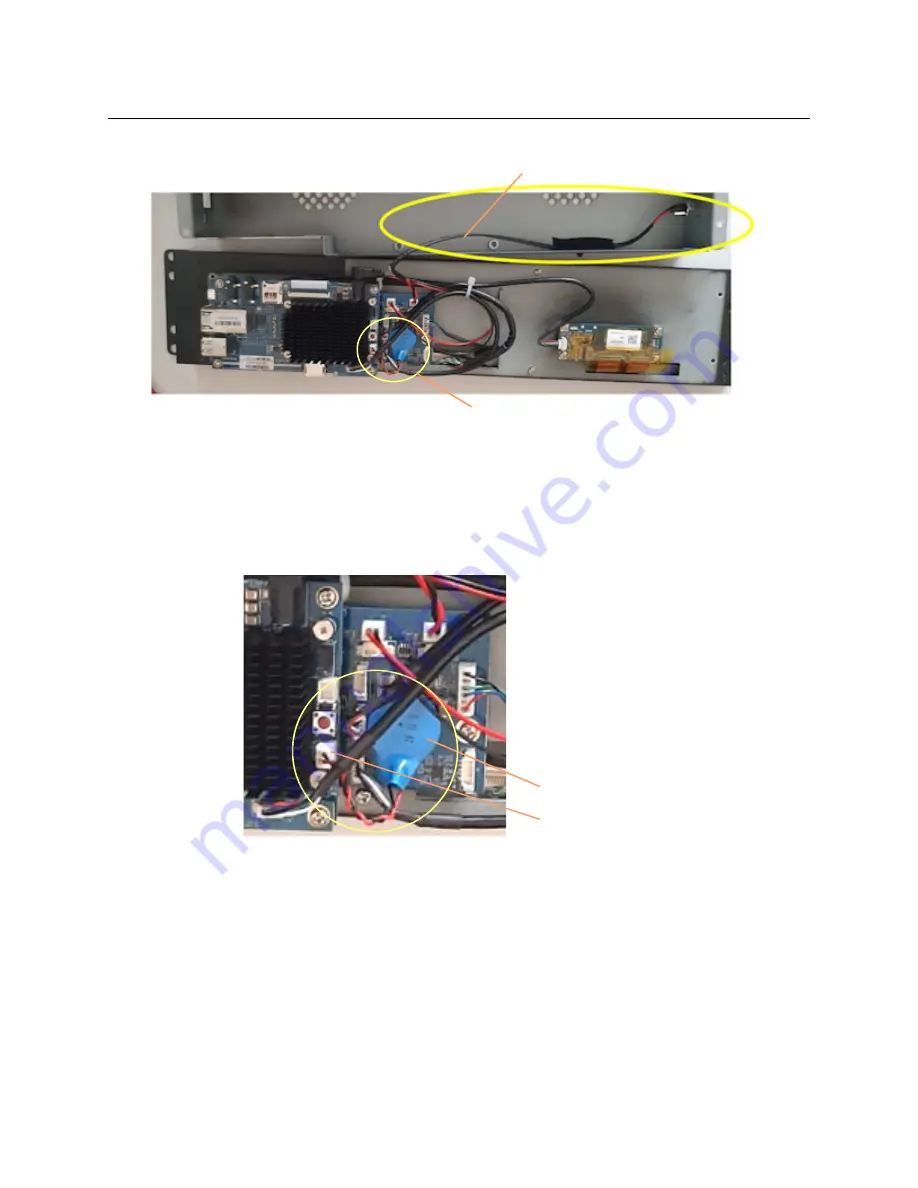
Fig. E-3: Rear Cover Removed
Now proceed to
.
Step 3: Remove Battery Unit
1 Locate the battery unit in the unit. It is a blue casing with a pair of wires (twisted black/
red) going to it from a white, 2-pin header-style connector.
Fig. E-4: Battery Unit Location
2 Disconnect the black/red twisted wires from the 2-pin header connector, noting the
orientation of the wires to the connector for reassembly.
Wire
Battery unit, blue casing
White 2-pin header-style connector
Battery unit, blue casing
Содержание ATP-2000
Страница 1: ...User Guide 13 03082 230 AA 24 November 2020 ATP 2000 ADVANCED TOUCH PANEL ...
Страница 4: ...iv Notices ...
Страница 21: ...xxi Table of Contents ...
Страница 25: ...4 Introduction This Document ...
Страница 41: ...20 Getting Started Configure Initial Settings in the Control Screen ...
Страница 47: ...26 ATP 2000 Control Screen Web Page ATP 2000 Control Screen Web Page ...
Страница 67: ...46 Maintenance Replacing the Battery ...
Страница 73: ...52 Hardware Specification External Connectors ...
Страница 75: ...54 Unit Dimensions ...
Страница 80: ...59 Power Supply Unit Power Supply Unit DC Power Supply Module 60 Physical 60 Electrical 60 ...
Страница 89: ...68 Battery Replacement Step 6 Re Install in Rack ...


