8935CF — Instruction Manual
51
Status Monitoring
When a red FAULT LED is lit on a frame front cover, the fault will also be
reported on the 8900NET or Frame Monitor module. The LEDs on the front
of these modules can then be read to determine the following fault condi-
tions:
•
Power Supply 1 and 2 health
•
Fan rotation status
•
Frame over-temperature condition
•
Frame Bus fault (8900NET only)
•
Module health bus
In general, LED colors used on the frame and modules indicate:
•
Green = normal operation, (Pass) or signal present, module locked.
•
Red – On continuously = fault condition, flashing = configuration error.
•
Yellow – On continuously = active condition (configuration mode or
communication), flashing in sequence = module locator function.
Status LEDs for this module are described in
8900NET module are described in the
8900NET Network Interface Instruction
Manual
.
Frame Alarm
A Frame Alarm connection is available on pins 8 and 9 of the RS-232 con-
nector on the rear of GeckoFlex frame (Frame Monitor or 8900NET
Network Interface module required). This will report any of the status
items enabled with the 8900NET or Frame Monitor module configuration
DIP switch. Connection and use of the Frame Alarm is covered in detail in
the
8900NET Network Interface Instruction Manual.
Web Browser Interface
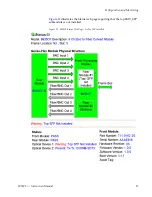
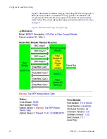
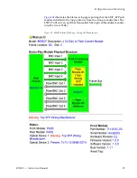
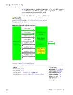
When the 8900NET module is installed in the frame, a web browser GUI
can indicate frame and module status on the following web pages:
•
Frame Status web page – reports overall frame and module status in
graphical and text formats.
•
Module Status web page – shows specific input and reference signal
status to the module along with module versions.
•
A Status LED icon on each web page to report communication status for
the frame slot and acts as a link to the Status page where warnings and
faults are displayed (8900NET version 3.0 or later).
Содержание 8935CF -
Страница 8: ...8 8935CF Instruction Manual Preface ...
Страница 58: ...58 8935CF Instruction Manual Index ...

