GRAPHTEC GL900 Скачать руководство пользователя страница 1

Checking the Outer Casing

Checking the Accessories

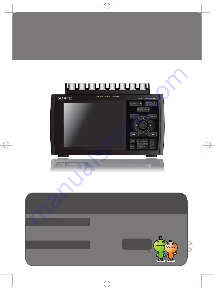
Thank you for purchasing the midi LOGGER GL900.

This Quick Start Guide describes the basic operations.

Please refer to the manual (PDF) in the CD-ROM for more information.

Don't forget to 

check the setting

o

 Quick Start Guide 

: 1

o

 CD-ROM

: 1

o

 AC cable/AC adapter  : 1

After unpacking, check the GL900's outer casing before use to make sure that there 

are no surface scratches or other flaws such as stains or dirt.

GL900

Quick Start Guide

midi LOGGER

GL900-UM-851

GL900-Quick-E.indd   1

08.5.15   3:27:26 PM

Содержание GL900

Страница 1: ...manual PDF in the CD ROM for more information Don t forget to check the setting o Quick Start Guide 1 o CD ROM 1 o AC cable AC adapter 1 After unpacking check the GL900 s outer casing before use to m...

Страница 2: ...9 2 Setup How to Make the Settings 10 3 Data Capture How to Capture Data 13 4 Data Replay How to Replay Captured Data 14 Convenient Functions 15 Timer Functions and Trigger Functions to Control Data...

Страница 3: ...LED POWER START CHARGE Battery cover Model imprint and others GND terminal AC adapter jack External input output terminals LOGIC PULSE EXT TRIG ALARM Power switch GL900 Part Names Top Panel Bottom Pan...

Страница 4: ...may cause damage to the measurement device Screw type terminal connection BNS terminal connection Direct voltage input Thermocouple input Direct current input Direct current Compensation copper wire...

Страница 5: ...rminals of the same channel at the same time It may cause damage to the measurement device Unused channels The analog input section has high impedance If it is open measurement signals may not be visi...

Страница 6: ...the channel and the and keys to change the setting values 14 NAVI 2 SPAN TRACE POSITION 3 TIME DIV 4 MENU 5 QUIT 1 CH SELECT 6 DIRECTION KEYS 7 ENTER 8 FAST FORWARD KEY KEY LOCK 9 START STOP USB DRIVE...

Страница 7: ...he cursor at high speed during a data replay operation and to change the operation mode in the file settings box Hold down both keys simultaneously for at least two seconds to enable key lock status T...

Страница 8: ...is key to clear the alarm The alarm settings are made in the TRIG menu Press the FILE key to save data to the GL900 s internal memory and to a USB memory device Press the NAVI key to display operation...

Страница 9: ...nerated 12 Pen display Displays the signal positions trigger positions and alarm ranges for each channel see right figure 13 File name display area Displays the data capture file name during the data...

Страница 10: ...objects Measurement points 2 locations Voltage range 1V Sampling interval 10ms Data save destination Internal RAM Number of capture points 10000 Auto save Internal flash memory Note If data is saved...

Страница 11: ...he ENTER key and the QUIT key The current cursor position is displayed in blue Use the keys to move the cursor If you press the ENTER key at the cursor position a selection menu or a box for inputting...

Страница 12: ...ber Internal RAM Internal flash memory and USB memory can be selected for Data Capture Destination Data can be recorded in the internal RAM at the sampling interval of 10 s or more but will be erased...

Страница 13: ...h the desired text and then press the ENTER key Finally move the cursor from the text selection area align it with the mark and then press the ENTER key 5 Return to screen 2 and align the cursor with...

Страница 14: ...es the data capture operation 3 Data Capture How to Capture Data Now that all the data capture settings have been made we will start actual data capture During the data capture operation let s also re...

Страница 15: ...ng of the cursor making of data search settings statistical calculation between cursor values X Y display and such can be performed Please try each of the functions 4 Data Replay How to Replay Capture...

Страница 16: ...ettings Timer Functions and Trigger Functions to Control Data Capture Start Stop Operations GL900 Convenient Functions 15 Points to Remember Here we will specify the timer condition as Enable data cap...

Страница 17: ...R 3 Set the CH1 mode to H 4 Open the Level Value Settings menu and set to 0 3V with the cursor and then press the ENTER key 5 Align the cursor to the button in the level menu settings and press the EN...

Страница 18: ...he waveform screen scale will be set to 0 25V to 0V 3 How to make a Trace setting The Trace parameter can be used to specify the waveform display of selected channels as On or Off 1 Press the SPAN POS...

Страница 19: ...C 2200 mAh two packs required Power consumption lAC power consumption when using the AC adapter provided as a standard accessory No 1 When the LCD is on 30VA 42VA 2 When the screensaver is operating 2...

Страница 20: ...S 100 200 TS 100 200 TS 100 100 TS 400 200 TS 100 Input terminal type Temperature Humidity Voltage Voltage Temperature BNC connectors All channels isolated Imbalanced input Simultaneous sampling of al...

Страница 21: ...00 Connect the PC and GL900 via a USB cable and power on the GL900 Installing the USB driver The Found New Hardware message appears followed by the Install New Hardware wizard for the environment sett...

Страница 22: ...lSpecifications are subject to change without notice GL900 Quick Start Guide GL900 UM 851 Publisher GRAPHTEC CORPORATION June 1 2008 1st edition 01 GL900 Quick E indd 22 08 5 15 3 27 56 PM...

Отзывы: