
Vortex Pro Combi – Internal Models
1. Remove front and top boiler casing panels.
Loosen (do not remove) the four screws
securing control panel to the side panels.
Hinge the panel forward to access top and
rear of control panel.
2. Remove the two screws and lift off the
terminal block cover from top of control
panel.
3. Remove both the Red and Black wire links
from terminals 17 & 18 and 19 & 20 on
control panel.
4. Carefully push through and remove square
pre-cut 'knockout' section in the control
panel front.
5. Connect
four
wires provided to terminals of
the electronic programmer – refer to Section
2 above.
Note that the
Yellow
wire supplied in the kit
must not be used.
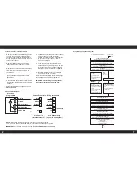
4. Connection diagram
6. Feed the wires through hole in control panel
front and then up through rectangular
opening in control panel top. Connect wires
to terminals on control panel – refer to
Connection diagram.
7. Locate the electronic programmer in the
square hole in control panel front – with the
terminals pointing to the
right
. Secure by
turning the two screws (in upper right and
lower left corners) a quarter turn clockwise.
8. Re-fit terminal block cover on control box
and fasten with the two screws.
Refer to the instructions on the following pages
for operating and setting the programmer.
IMPORTANT: After fitting the programmer
leave these instructions with the User.
2
1
3
4
5
M
Electronic
programmer
N - Blue
L - Brown
HW On - Orange
HW Off - Yellow
CH On - Red
21
Blue
Brown
Orange
Red
22
17
19
2
Blue
Brown
Orange
Red
1
7
Yellow
6
5
Vortex Pro Boilers - Wiring terminals
Pro Combi e
(internal models)
Pro Kitchen/Utility
(system & non-system)
NOTE:
When using the EP kit with an ‘S-plan’ type control system (using
2 x 2 - port zone valves) the YELLOW wire is not required and should not be used.
IMPORTANT -
For Vortex Pro Combi e boilers the
YELLOW wire must not be used
.
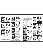
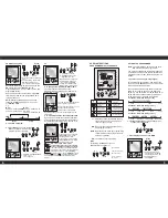
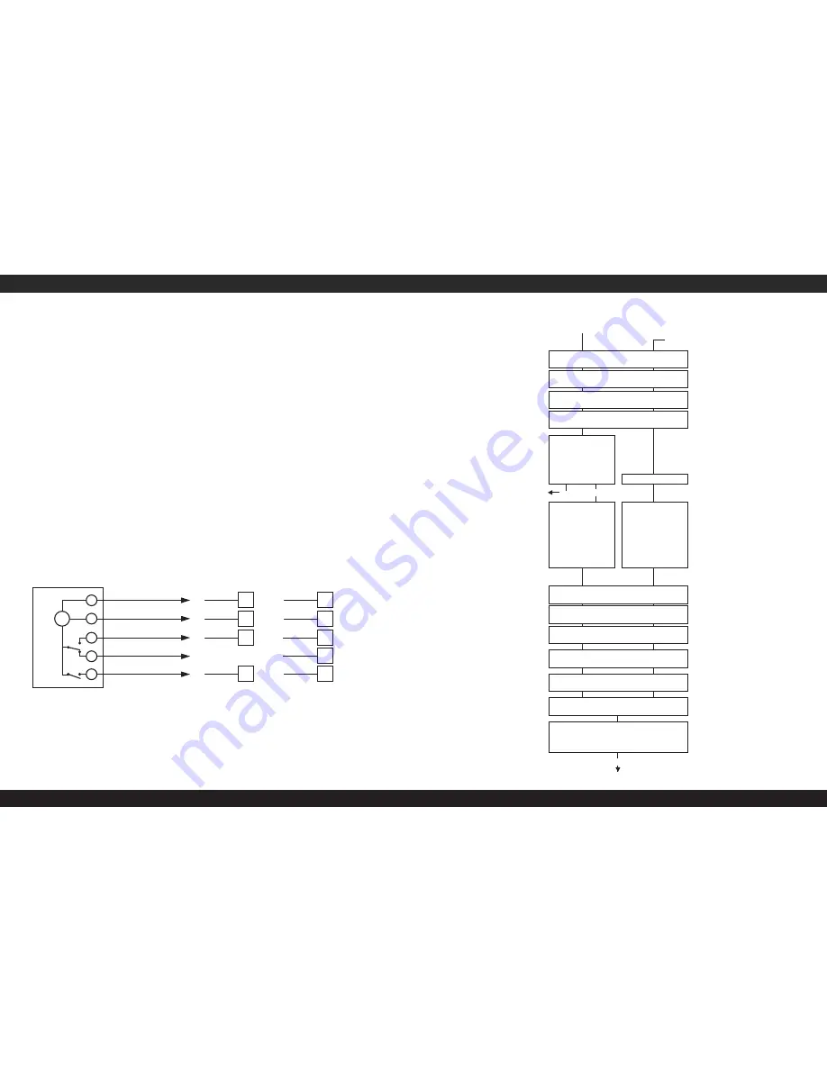
Programming sequence diagram
Reset (first installation adjustment)
Review/adjust
Menu
Set time: Hour
Hour blinking, using
to select, then OK
+/-
to confirm
Set time: Format 24h or am/pm
24h blinking, using
+/-
to select, then OK to confirm
Set time: Minute
Minute blinking, using
to select, then OK
+/-
to confirm
Set time: Day
Monday (1) blinking, using
to select, then OK
+/-
to confirm
Set Program: P01/ P02/ P03
or P--
Using +/- to select, then OK
To set ON/OFF times
Or
Press Menu to terminate
programming
Note:
P01-P03
are pre-set
P01is pre-set
Set Program: P01/ P02/ P03
or P– –
Setting switching times:
First free memory location
blinks
Press
‘-’
to go back one
memory location
Press OK for setting the
switching times.
Menu
OK
Prog01
Setting switching times:
First free memory location
blinks
Press OK for setting the
switching times.
Set switching ON time:Hour
Hour blinking, using
to select, then OK
+/-
to confirm
Set switching ON time:Minute
Minutes blinking, using
to select, then OK
+/-
to confirm
Set switching ON time:Days
Mon Su (1 7) blinking, using
to select, then OK
+/-
to confirm
Set display: channel 1 or 2
Ch1 blinking, using
to select, then OK
+/-
to confirm
Set switching OFF time:Hour
Hour blinking, using
to select, then OK
+/-
to confirm
Set switching OFF time:Mnute
Minute blinking, using
to select, then OK/Menu
+/-
to confirm
A maximum of 20 memory locations
can be occupied:
10 switching ON times
10 switching OFF times
Menu
Run
7
2
(see note)


