


INSTALLATION INSTRUCTIONS
R
−
410A Split System Heat Pump
2
428 01 5301 05
Specifications subject to change without notice.
INSPECT NEW UNIT
After uncrating unit, inspect thoroughly for hidden
damage. If damage is found, notify the transportation
company immediately and file a concealed damage
claim.
SAFETY CONSIDERATIONS
Consult a qualified installer, service agency, or the
dealer/distributor for information and assistance. The
qualified installer must use factory authorized kits and
accessories when modifying this product. Refer to the
individual instructions packaged with the kit or accessory
when installing.
The weight of the product requires careful and proper
handling procedures when lifting or moving to avoid
personal injury. Use care to avoid contact with sharp or
pointed edges.
Follow all safety codes. Wear safety glasses, protective
clothing, and work gloves. Use a heat sinking material
−
such as a wet rag
−
during brazing operations. Keep a fire
extinguisher available. Consult local codes and the
National Electric Code (NEC) for special requirements.
Improper installation, adjustment, alteration, service or
maintenance can void the warranty
.
!
CAUTION
CUT HAZARD
Failure to follow this caution may result in proper-
ty damage.
Sheet metal parts may have sharp edges or burrs.
Use care and wear appropriate protective clothing
and gloves when handling parts.
!
WARNING
ELECTRICAL SHOCK HAZARD
Failure to follow this warning could result in
personal injury or death.
Before installing, modifying or servicing system,
main electrical disconnect switch must be in the
OFF position. There may be more than 1
disconnect switch. Lock out and tag switch with a
suitable warning label.
!
CAUTION
PROPERTY DAMAGE HAZARD
Failure to follow this caution may result in proper-
ty damage
R
−
410A systems operate at higher pressures than
R
−
22 systems. When working with R
−
410A sys-
tems, use only service equipment and replace-
ment components specifically rated or approved
for R
−
410A service.
LOCATION
Check local codes for regulations concerning zoning,
noise, platforms, and other issues.
Locate unit away from fresh air intakes, vents, or
bedroom windows. Noise may carry into the openings
and disturb people inside.
Locate unit in a well drained area, or support unit high
enough so that water runoff will not enter the unit.
Locate unit away from areas where heat, lint, or exhaust
fumes will be discharged onto unit (as from dryer vents).
Locate unit away from recessed or confined areas where
recirculation of discharge air may occur (refer to
CLEARANCES section of this document).
Roof
−
top installation is acceptable providing the roof will
support the unit and provisions are made for water
drainage and noise/vibration dampening.
NOTE:
Roof mounted units exposed to wind may require
wind baffles. Consult the manufacturer for additional
information.
CLEARANCES
When installing, allow sufficient space for airflow
clearance, wiring, refrigerant piping, and service. Allow
24 in. (610 mm) clearance to service end of unit and 48
in. (1219.2 mm) above unit. For proper airflow, a 6 in.
(152.4 mm) clearance on one side of unit and 12 in.
(304.8 mm) on all remaining sides must be maintained.
Maintain a distance of 24 in. (609.6 mm) between units
or 18 in. (457.2 mm) if no overhang within 12 ft.
(3.66m). Position so water, snow, or ice from roof or
eaves cannot fall directly on unit.
On rooftop applications, locate unit at least 6 in.
(152.4mm) above roof surface.
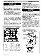
UNIT SUPPORT
NOTE:
Unit must be level
|
2 degrees {
a
inch rise or3/8 fall
per foot of run (10mm rise or fall per 305 mm of run) } or
compressor may not function properly.
A. GROUND LEVEL INSTALLATION
The unit must be level and supported above grade by
beams, platform, or a pad. Platform or pad can be of open or
solid construction but should be of permanent materials
such as concrete, bricks, blocks, steel, or pressure
−
treated
timbers approved for ground contact. Soil conditions must
be considered so that the platform or pad does not shift or
settle and leave the unit partially supported. Minimum pad
dimensions are shown in Figure 2.
If beams or an open platform are used for support, it is
recommended that the soil be treated or area be graveled
to reduce the growth of grasses and weeds.
To minimize vibration or noise transmission, it is
recommended that supports not be in contact with the
building structure. However, slabs on grade constructions
with an extended pad are normally acceptable.


