Voice Broadband Optical Multiplexer
User
Manual
5
Chpater 2 Function Description
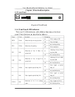
2.1 Front Panel
PW
R
SY
L
E6
E1
L2
A
C
T1
A
C
T2
SY
S
D
U
P1
D
U
P2
SP
D
1
SP
D
2
E1
L1
LO
S
E3
V
1
V
3
V
5
V
7
V
9
V
11
V
13
V
15
V
17
V
19
V
21
V
23
V
27
V
25
V
29
V
31
V
2
V
4
V
6
V
8
V
10
V
12
V
14
V
16
V
18
V
20
V
22
V
24
V
28
V
26
V
30
V
32
CONSOLE
TX
RX
Fiber Port
E1
L4
E1
L3
A
C
T4
D
U
P3
D
U
P4
SP
D
3
SP
D
4
A
C
T3
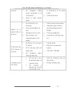
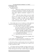
(Figure of Front Panel)
2.1.1 Front Panel LED Indicators
There are 52 LED indicators with different functions at the front
panel. Their functions are described as follows:
Name
Color
Function
Description
PWR
Green
Indication of power supply status
on
Power supply is OK.
off
No power input.
SYS
Yellow
Indication of operating
on
In normal operation.
off
Not in operation.
SYL
Red
Indication of loss of frame in
optical link
on
Alarming of loss of frame
in optical link.
off
In normal operation.
LOS
Red
Indication of loss of signal in
optical link
on
Alarming of loss of signal
in optical link.
off
In normal operation.
E6
Yellow
Error signal in optical link≥10-6
on
Error signal in optical
link≥10
-6
off
In normal operation.
E3
Red
Error signal in optical link≥10-3
on
Error signal in optical
link≥10
-3
off
In normal operation.
E1L1-4
Red
Indication of E1 1-4 working
status
on
Loss of signal in E1 1st
off
In normal operation.


