


11
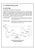
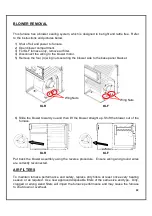
5.0 BURNER INSTALLATION AND SPECIFICATIONS
5.1 ASSEMBLY & INSTALLATION OF BURNER
ASSEMBLY
Check that the burner model is correct for furnace rating required.
Assemble as per burner manufacturer’s instructions.
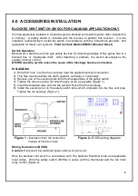
SELECT NOZZLE
Select oil input, nozzle and burner configuration as shown on furnace
operating decal.
INSTALL NOZZLE
Install selected nozzle, check for clean seating and tighten in nozzle
adaptor.
ELECTRODES
See burner manufacturer’s instructions for correct setting
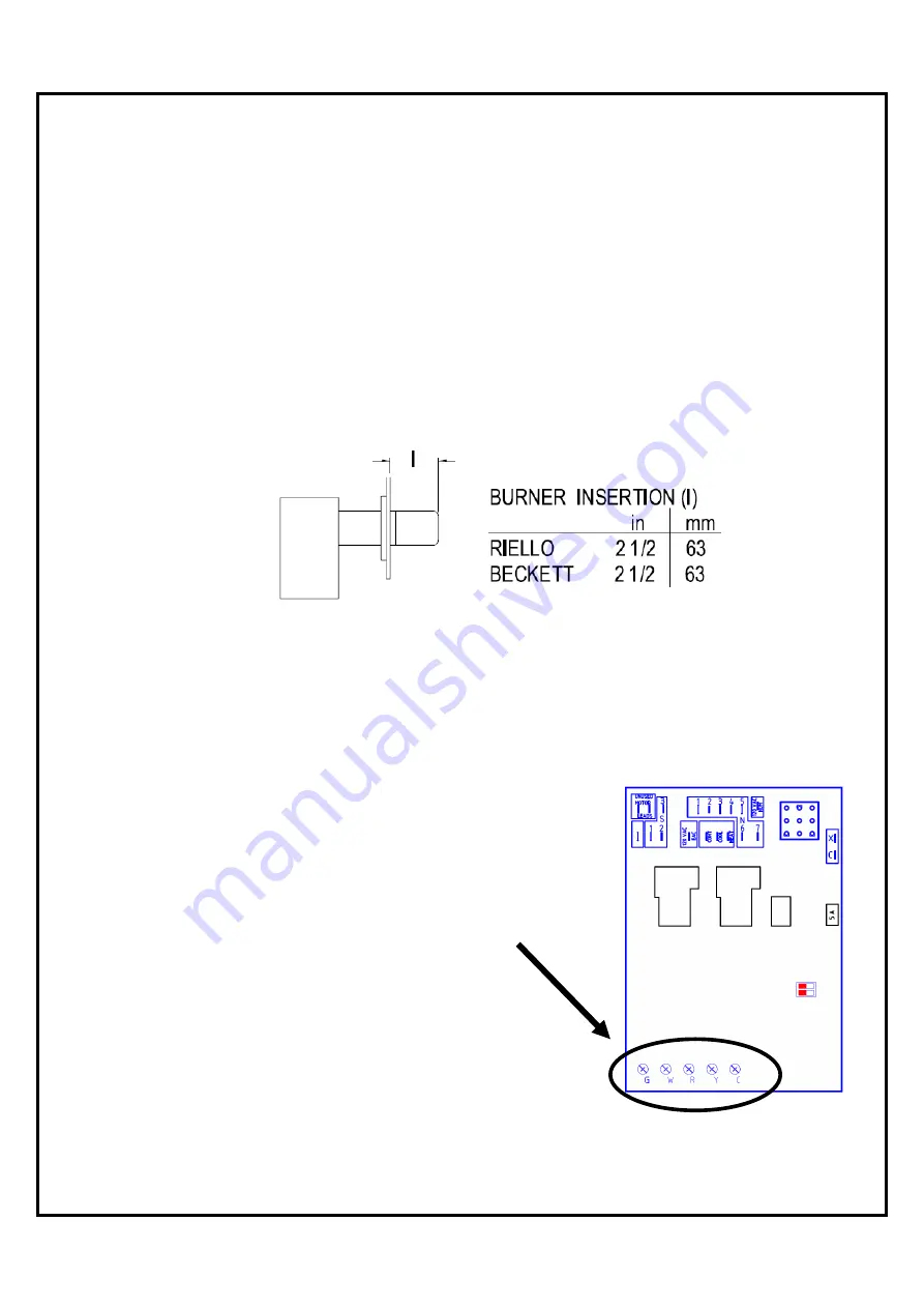
INSERTION
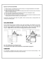
MOUNT BURNER
Tighten top nut first so burner tips down
slightly. The burner is always installed in
an upright position by four (4) nuts.
PUMP BY-PASS
For one pipe system factory setting (no
PLUG
plug).
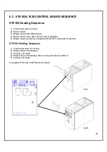
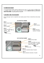
WIRING
Refer to wiring diagram for correct burner
connections (see page 24 or 25).
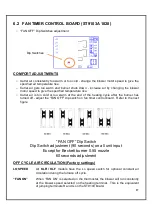
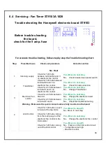
THERMOSTAT
Connect the thermostat wires to the fan
timer control board (ST9103).
Содержание KLF-200
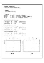
Страница 7: ...6 KLR 200 DIMENSIONS Dimensions are in inches KLF 200 DIMENSIONS Dimensions are in inches...
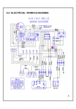
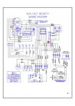
Страница 25: ...24 8 0 ELECTRICAL WIRING DIAGRAMS...
Страница 26: ...25...
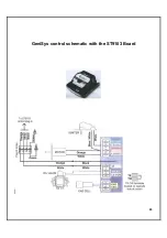
Страница 27: ...26 GeniSys control schematic with the ST9103 Board...
Страница 28: ...27 9 0 EXPLODED PARTS VIEW KLR 100 Exploded Parts View...
Страница 30: ...29 KLR 200 Exploded Parts View...
Страница 32: ...31 KLF 200 Exploded Parts View...


