


11
308854
Pressure Control Repair
8185A
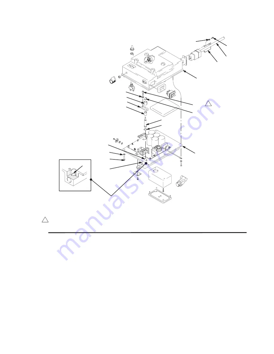
Fig 8
214
202
213
201
90 REF
230
89 REF
229
214
216
217
213
215
218
219
220
1
Torque to 150 in–lb (17 N.m)
C
A
B
1
2.
Carefully slide new o–ring (220) down bore (A) of
motor control (201) into o–ring groove (B). Make
sure o–ring is in groove around its entire circumfer-
ence.
NOTE:
P
T
FE
o–ring (220) is stiffer than a rubber
o–ring and may be difficult to place in groove.
3.
Carefully slide new transducer and plastic
spacer (217) down bore. Loosely attach
bracket (218), screws (213), and washers (214).
4.
Seat transducer into o–ring by drawing down
screws and washers until bracket is flush with
motor control surface.
5.
Carefully remove transducer and verify that o–ring
is seated correctly and not pushed out of groove. If
not seated correctly use new o–ring and repeat
steps 2 through 5.
6.
When o–ring is correctly installed, reinstall trans-
ducer and tighten screws to 150 in-lb (17 N
m).
Install spacer (216) and C-clip (215). Connect
electrical lead and assemble sprayer.
7.
Perform Flush and Prime procedures in STARTUP
of Operation Manual 308855 with compatible fluid.
8.
Inspect weep hole (C) for any leakage.
9.
If any leakage is present, replace o–ring repeating
steps 1 through 9.