


Warnings
3A5413F
3
Warnings
The following warnings are for the setup, use, grounding, maintenance, and repair of this
equipment. The exclamation point symbol alerts you to a general warning and the hazard
symbols refer to procedure-specific risks. When these symbols appear in the body of this
manual or on warning labels, refer back to these Warnings. Product-specific hazard symbols
and warnings not covered in this section may appear throughout the body of this manual where
applicable.
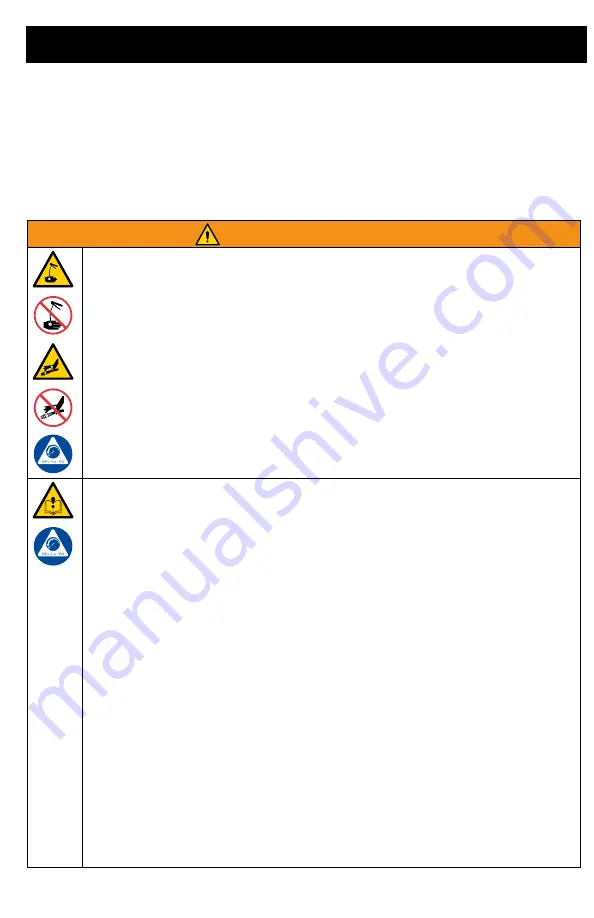
WARNING
SKIN INJECTION HAZARD
High-pressure fluid from dispensing device, hose leaks, or ruptured components
will pierce skin. This may look like just a cut, but it is a serious injury that can result
in amputation.
Get immediate surgical treatment.
•
Do not point dispensing device at anyone or at any part of the body.
•
Do not put your hand over the fluid outlet.
•
Do not stop or deflect leaks with your hand, body, glove, or rag.
•
Follow the
Pressure Relief Procedure
when you stop dispensing and before
cleaning, checking, or servicing equipment.
•
Tighten all fluid connections before operating the equipment.
•
Check hoses and couplings daily. Replace worn or damaged parts immediately.
EQUIPMENT MISUSE HAZARD
Misuse can cause death or serious injury.
•
Do not operate the unit when fatigued or under the influence of drugs or alcohol.
•
Do not exceed the maximum working pressure or temperature rating of the low-
est rated system component. See
Technical Specifications
in all equipment
manuals.
•
Use fluids and solvents that are compatible with equipment wetted parts. See
Technical Specifications
in all equipment manuals. Read fluid and solvent
manufacturer’s warnings. For complete information about your material, request
Safety Data Sheets (SDSs) from distributor or retailer.
•
Turn off all equipment and follow the
Pressure Relief Procedure
when equip-
ment is not in use.
•
Check equipment daily. Repair or replace worn or damaged parts immediately
with genuine manufacturer’s replacement parts only.
•
Do not alter or modify equipment. Alterations or modifications may void agency
approvals and create safety hazards.
•
Make sure all equipment is rated and approved for the environment in which you
are using it.
•
Use equipment only for its intended purpose. Call your distributor for information.
•
Route hoses and cables away from traffic areas, sharp edges, moving parts, and
hot surfaces.
•
Do not kink or over bend hoses or use hoses to pull equipment.
•
Keep children and animals away from work area.
•
Comply with all applicable safety regulations.
Содержание Pulse 25M317
Страница 23: ...Notes 3A5413F 23 Notes...


