


Connect Input/Output (I/O) Signals
10
3A8812B
Electric EEO Option
1. Plug the
EEO bulkhead fitting (J) on the cabinet
with a 5/32 in. plug (18).
2. Run a signal wire and a ground wire through the I/O
strain relief ports on the right side of the system.
See F
. 7.
3. Feed these wires through the top right opening in
the electronics control panel.
4. Connect terminal block 11 (C11) to the gun's
electrostatic controller with the signal wire.
- When the output is inactive terminal block 11
(C11) has 4-5V present.
- When the output is active there is 24V present.
5. Connect terminal block 12 (C12) to the ground wire.
NOTE:
Terminal block 11 (C11) signal voltage is
optically isolated at Graco electrostatic controllers. If
using any other controller be sure to use an
optocoupler at the input to the device.
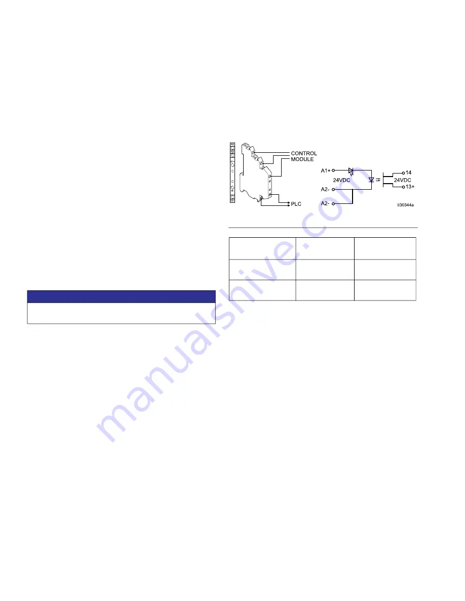
Wire LPO Optocoupler
1. LPO optocoupler (B) ports A1+ and A2– are wired
to the control module.
2. Wire LPO optocoupler (B) ports 13+ and 14 to an
external device or PLC.
NOTICE
To prevent damage to equipment, do not use these
terminal blocks without an optocoupler present.
F
IG
. 9 Low paint output wiring
Function
A1+ (relative to
A2–)
PLC
Low Paint Output
Active
24 VDC
13+ and 14
connected
Low Paint Output
Inactive
Less than 13.5
VDC
13+ and 14 not
connected


