background image

2

313872B

Contents

Related Manuals . . . . . . . . . . . . . . . . . . . . . . . . . . . 3

Models . . . . . . . . . . . . . . . . . . . . . . . . . . . . . . . . . . . 4

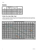
Orifice Flow Area Ratio Chart . . . . . . . . . . . . . . . 4

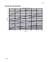
Fixed Orifice Flowrate Data . . . . . . . . . . . . . . . . . 5

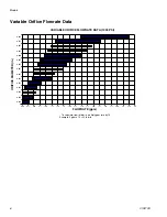
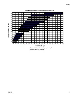
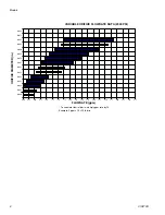
Variable Orifice Flowrate Data . . . . . . . . . . . . . . 6

Warnings . . . . . . . . . . . . . . . . . . . . . . . . . . . . . . . . . 9

Important Two-Component Material Information 11

Isocyanate Conditions . . . . . . . . . . . . . . . . . . . . 11

Material Self-ignition . . . . . . . . . . . . . . . . . . . . . 11

Keep Components A and B Separate . . . . . . . . 11

Moisture Sensitivity of Isocyanates . . . . . . . . . . 11

Foam Resins with 245 fa Blowing Agents . . . . . 11

Changing Materials . . . . . . . . . . . . . . . . . . . . . . 12

A (Red) and B (Blue) Components . . . . . . . . . . 12

Throat Seal Liquid . . . . . . . . . . . . . . . . . . . . . . . . . 13

Grounding . . . . . . . . . . . . . . . . . . . . . . . . . . . . . . . 13

Piston Safety Lock . . . . . . . . . . . . . . . . . . . . . . . . 13

Trigger Lock . . . . . . . . . . . . . . . . . . . . . . . . . . . . . . 13

Loss of Air Pressure . . . . . . . . . . . . . . . . . . . . . . . 14

Hook Support . . . . . . . . . . . . . . . . . . . . . . . . . . . . . 14

Component Identification . . . . . . . . . . . . . . . . . . . 16

Cutaway View . . . . . . . . . . . . . . . . . . . . . . . . . . 17

Theory of Operation . . . . . . . . . . . . . . . . . . . . . . . 18

Gun Triggered (Fluid Pouring) . . . . . . . . . . . . . 18

Gun Detriggered . . . . . . . . . . . . . . . . . . . . . . . . 18

Setup . . . . . . . . . . . . . . . . . . . . . . . . . . . . . . . . . . . . 19

Adjust Orifices . . . . . . . . . . . . . . . . . . . . . . . . . . 20

Optional Hose Position . . . . . . . . . . . . . . . . . . . 21

Pressure Relief Procedure . . . . . . . . . . . . . . . . . . 22

Shutdown . . . . . . . . . . . . . . . . . . . . . . . . . . . . . . . . 23

Short Term Shutdown . . . . . . . . . . . . . . . . . . . . 23

Long Term Shutdown . . . . . . . . . . . . . . . . . . . . 23

Maintenance . . . . . . . . . . . . . . . . . . . . . . . . . . . . . . 24

Supplied Tool Kit . . . . . . . . . . . . . . . . . . . . . . . . 24

Lubrication . . . . . . . . . . . . . . . . . . . . . . . . . . . . 24

Bleed Throat Seal Liquid Cartridge . . . . . . . . . . 24

Flush Gun . . . . . . . . . . . . . . . . . . . . . . . . . . . . . 25

Clean Outside of Gun . . . . . . . . . . . . . . . . . . . . 25

Clean Breather Plug . . . . . . . . . . . . . . . . . . . . . 26

Clean Fluid Manifold . . . . . . . . . . . . . . . . . . . . . 26

Clean Check Valves . . . . . . . . . . . . . . . . . . . . . 27

Clean Fluid Housing Passages . . . . . . . . . . . . . 28

Clean Orifice . . . . . . . . . . . . . . . . . . . . . . . . . . . 29

Replace Mix Chamber and Front Seal . . . . . . . 30

Repair . . . . . . . . . . . . . . . . . . . . . . . . . . . . . . . . . . . 31

Tools Required . . . . . . . . . . . . . . . . . . . . . . . . . 31

Lubrication . . . . . . . . . . . . . . . . . . . . . . . . . . . . . 31

Replace Throat Seal Liquid Cartridge

. . . . . . . 31

Remove Front End . . . . . . . . . . . . . . . . . . . . . . 33

Disassemble Front End . . . . . . . . . . . . . . . . . . . 34

Assemble Front End . . . . . . . . . . . . . . . . . . . . . 34

Attach Front End . . . . . . . . . . . . . . . . . . . . . . . . 35

Pistons and Bulkhead . . . . . . . . . . . . . . . . . . . . 35

Purge Rod . . . . . . . . . . . . . . . . . . . . . . . . . . . . . 37

Solenoid Valve . . . . . . . . . . . . . . . . . . . . . . . . . . 38

Troubleshooting . . . . . . . . . . . . . . . . . . . . . . . . . . . 39

Electrical Diagram . . . . . . . . . . . . . . . . . . . . . . . 41

Parts . . . . . . . . . . . . . . . . . . . . . . . . . . . . . . . . . . . . 42

Kits . . . . . . . . . . . . . . . . . . . . . . . . . . . . . . . . . . . . . 45

Orifice Kits . . . . . . . . . . . . . . . . . . . . . . . . . . . . . 50

Drill Bit Kits . . . . . . . . . . . . . . . . . . . . . . . . . . . . 51

Complete O-ring Placement Guide . . . . . . . . . . 52

Accessories . . . . . . . . . . . . . . . . . . . . . . . . . . . . . . 53

Lubricant for Gun Rebuild . . . . . . . . . . . . . . . . . 53

Throat Seal Liquid Cartridges . . . . . . . . . . . . . . 53

Fluid Inlet Cover . . . . . . . . . . . . . . . . . . . . . . . . 53

Gun Cleaning Kit . . . . . . . . . . . . . . . . . . . . . . . . 53

Flushing Manifold . . . . . . . . . . . . . . . . . . . . . . . 53

15B817 Manifold Block . . . . . . . . . . . . . . . . . . . 53

Circulation Manifold . . . . . . . . . . . . . . . . . . . . . . 53

Reactor IP Harness . . . . . . . . . . . . . . . . . . . . . . 53

Solvent Flush Canister Kit . . . . . . . . . . . . . . . . . 54

Solvent Flush Pail Kit . . . . . . . . . . . . . . . . . . . . . 54

Technical Data . . . . . . . . . . . . . . . . . . . . . . . . . . . . 55

Dimensions . . . . . . . . . . . . . . . . . . . . . . . . . . . . 56

Graco Standard Warranty . . . . . . . . . . . . . . . . . . . 58

Graco Information . . . . . . . . . . . . . . . . . . . . . . . . . 58

Содержание EP 24C932

Страница 1: ...use in explosive atmospheres Model 257999 24C932 24C933 24C934 3000 psi 20 7 MPa 207 bar Maximum Fluid Working Pressure 80 100 psi 0 55 0 69 MPa 5 5 6 9 bar Air Inlet Pressure Range 180 F 82 C Maximum Fluid Temperature US Patent Pending Important Safety Instructions Read all warnings and instructions in this manual Save these instructions TI14450a 313872B ENG ...

Страница 2: ...own 23 Maintenance 24 Supplied Tool Kit 24 Lubrication 24 Bleed Throat Seal Liquid Cartridge 24 Flush Gun 25 Clean Outside of Gun 25 Clean Breather Plug 26 Clean Fluid Manifold 26 Clean Check Valves 27 Clean Fluid Housing Passages 28 Clean Orifice 29 Replace Mix Chamber and Front Seal 30 Repair 31 Tools Required 31 Lubrication 31 Replace Throat Seal Liquid Cartridge 31 Remove Front End 33 Disassem...

Страница 3: ...nuals in U S English Power LockTM Heated Hose Part Description 309572 Instructions Parts Solvent Flush Kits Part Description 309963 Instructions Parts Circulation Manifold Kit Part Description 309818 Instructions Parts Heated Hoses and Applicator Kits Part Description 3A0237 Instructions Parts ...

Страница 4: ...9 9 11 2 13 3 18 5 0 024 2 3 1 4 1 0 1 4 1 7 2 1 2 6 3 1 3 8 4 7 5 3 6 3 6 9 7 8 9 3 12 8 0 028 3 1 2 0 1 4 1 0 1 2 1 6 1 9 2 3 2 8 3 4 3 9 4 6 5 1 5 7 6 8 9 4 0 031 3 8 2 4 1 7 1 2 1 0 1 3 1 6 1 8 2 3 2 8 3 1 3 7 4 1 4 7 5 5 7 7 0 035 4 8 3 1 2 1 1 6 1 3 1 0 1 2 1 4 1 8 2 2 2 5 2 9 3 2 3 7 4 4 6 0 0 039 5 9 3 8 2 6 1 9 1 6 1 2 1 0 1 2 1 5 1 8 2 0 2 4 2 6 3 0 3 5 4 9 0 042 6 9 4 4 3 1 2 3 1 8 1 4 ...

Страница 5: ... 00 1 25 1 50 1 75 2 00 2 25 2 50 2 75 3 00 3 25 3 50 3 75 4 00 4 25 4 50 4 75 5 00 500 750 1000 1250 1500 1750 2000 Pressure psi Flow gpm 0 020 in Diameter Orifice 0 031 in Diameter Orifice 0 047 in Diameter Orifice 0 060 in Diameter Orifice 0 067 in Diameter Orifice 0 086 in Diameter Orifice ...

Страница 6: ... 1 50 1 75 2 00 2 25 2 50 2 75 3 00 3 25 3 50 3 75 4 00 4 25 4 50 4 75 0 020 0 024 0 028 0 031 0 033 0 039 0 041 0 047 0 052 0 055 0 060 0 063 ORIFICE DIAMETER in FLOWRATE gpm To calculate flow in lb min multiply gpm rate by 10 Example 2 gpm x 10 20 lb min VARIABLE ORIFICE FLOWRATE DATA 1000 PSI ...

Страница 7: ...00 3 25 3 50 3 75 4 00 4 25 4 50 4 75 0 020 0 024 0 028 0 031 0 033 0 039 0 041 0 047 0 052 0 055 0 060 0 063 0 067 0 073 0 086 ORIFICE DIAMETER in FLOWRATE gpm To calculate flow in lb min multiply gpm rate by 10 Example 2 gpm x 10 20 lb min VARIABLE ORIFICE FLOWRATE DATA 1500 PSI ...

Страница 8: ...00 3 25 3 50 3 75 4 00 4 25 4 50 4 75 0 020 0 024 0 028 0 031 0 033 0 039 0 041 0 047 0 052 0 055 0 060 0 063 0 067 0 073 0 086 ORIFICE DIAMETER in FLOWRATE gpm To calculate flow in lb min multiply gpm rate by 10 Example 2 gpm x 10 20 lb min VARIABLE ORIFICE FLOWRATE DATA 2000 PSI ...

Страница 9: ...protect you from serious injury including eye injury hearing loss inhala tion of toxic fumes and burns This equipment includes but is not limited to Protective eyewear and hearing protection Respirators protective clothing and gloves as recommended by the fluid and solvent manufac turer SKIN INJECTION HAZARD High pressure fluid from dispensing device hose leaks or ruptured components will pierce s...

Страница 10: ...at are compatible with equipment wetted parts See Technical Data in all equipment manuals Read fluid and solvent manufacturer s warnings For complete information about your material request MSDS from distributor or retailer Do not leave the work area while equipment is energized or under pressure Turn off all equipment and follow the Pressure Relief Procedure when equipment is not in use Check equ...

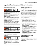
Страница 11: ...ers closed when not in use Never use solvent on one side if it has been contam inated from the other side Always lubricate threaded parts with ISO pump oil or grease when reassembling Foam Resins with 245 fa Blowing Agents Some foam blowing agents will froth at temperatures above 90 F 33 C when not under pressure especially if agitated To reduce frothing minimize preheating in a circulation system...

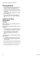
Страница 12: ...nts IMPORTANT Material suppliers can vary in how they refer to plural component materials Be aware that when standing in front of the manifold on proportioner Component A Red is on the left side The A Red side is intended for ISO hardeners and catalysts Component B Blue is on the right side The B Blue side is intended for polyols resins and bases For ratios higher than 1 1 the higher volume is typ...

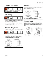
Страница 13: ...gage To engage piston safety lock push knob in and turn clockwise If engaged gun will not dispense Disengage To disengage piston safety lock push knob in and turn counterclockwise until it pops out There will be a gap between knob and gun body Trigger Lock Engage trigger lock whenever you stop pouring to avoid accidental triggering Must be used with piston safety lock Read material MSDS to know sp...

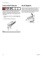
Страница 14: ...do one of the following Engage piston safety lock see Piston Safety Lock section Close fluid valves A and B see FIG 3 Hook Support If necessary use the hook support located on the top of the gun to support the weight of the gun Connect a strong rope or chain able to support the weight of the gun to the hook then connect the other end to a sup port This will enable the user to use the gun without h...

Страница 15: ...Hook Support 313872B 15 ...

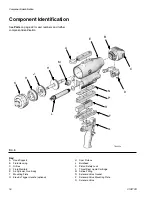
Страница 16: ...ok Support B Fluid Housing C Orifice D Fluid Manifold E Air Cylinder Gun Body F Mounting Plate G Electric Trigger Handle optional H Dual Pistons J Bulkhead K Piston Safety Lock L Throat Seal Liquid Cartridge M Airline Fitting N Solenoid Valve Gasket P Solenoid Valve Mounting Plate R Solenoid Valve FIG 4 TI14451a A B C D E F G H H J K L M N R P ...

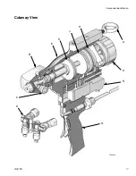
Страница 17: ...Component Identification 313872B 17 Cutaway View TI14462a D K E B G R H J H A C ...

Страница 18: ...id to mix and flow through the nozzle Throat Seal Liquid lubricates the purge rod Gun Detriggered Purge rod extends closing the impingement ports and stopping fluid flow Throat Seal Liquid lubricates the purge rod Purge Rod TI14476a Throat Seal Liquid Side View Top View TI14485a Purge Rod TI14477a Throat Seal Liquid Side View Top View TI14486a ...

Страница 19: ...n on air Open air valve AB See FIG 6 7 Connect signal cable to solenoid valve 8 Models with a handle connect signal cable to han dle 9 Disengage piston safety lock See page 13 10 Verify fluid valves are closed see FIG 5 then trigger gun to check for full purge rod travel FIG 5 TI2411a A B TI2417a FIG 6 In the following step do not point gun at yourself If necessary use a mirror to verify purge rod...

Страница 20: ...ce can achieve the desired pressure both orifices should be replaced with a larger or smaller size Note that a smaller orifice will provide higher pressure and a larger orifice will pro vide lower pressure If after attempting to balance pressures the pressure dif ference is over 500 psi one orifice should be replaced with a different size If that is the case adjust the needle in each orifice all t...

Страница 21: ...pply thread sealant to plugs AH elbows AJ and male threads of swivels AE Install elbows AJ in optional inlets facing down See FIG 11 Install swivels in elbows Be sure to install the A swivel in the A side Install plugs AH where swivels had been Torque all parts to 235 245 in lb 26 6 27 7 N m 6 Connect the A hose to the A swivel and the B hose to the B swivel 7 Attach fluid manifold AD to gun Torqu...

Страница 22: ...4 Trigger gun onto cardboard or into waste container to relieve pressure 5 Disconnect air quick coupler AC See FIG 12 6 Engage piston safety lock See page 13 7 Relieve system pressure See Pressure Relief Pro cedure in proportioner manual 8 Ensure fluid valves are closed then remove fluid manifold 9 Place the fluid manifold over waste containers fac ing away from you 10 Very slowly open the fluid v...

Страница 23: ...ston safety lock engaged in order to ensure material does not build up on the purge rod When purge rod is retracted spray some Throat Seal Lubricant into the front nose 3 Leave air turned on and gun detriggered 4 Remove any material build up on front of gun Long Term Shutdown Perform Long Term Shutdown procedure if gun will not be used for more than 48 hours 1 Perform Short Term Shutdown 2 Flush G...

Страница 24: ...use a 5 16 in nut driver sup plied to slowly open the bleed valve 1 4 to 1 2 turn until air fluid begins to slowly exit the valve See FIG 15 2 When no more air comes out of the bleed valve close the bleed valve Procedure Schedule Bleed Throat Seal Liquid Car tridge page 24 Weekly Replace Mix Chamber and Front Seal see page 30 Every 2 4 Weeks Clean Clean Check Valves page 27 Monthly Clean Outside o...

Страница 25: ...re available as an accessory See Accessories on page 53 7 Remove flush hoses from flush manifold Remove flush manifold from gun 8 Remove Recirculation Block 15C850 from fluid manifold 9 Connect fluid manifold to gun Torque fluid manifold bolt to 20 30 in lb 2 26 3 39 N m 10 Connect signal cable Clean Outside of Gun Wipe the outside of the gun with a compatible solvent See materials of construction...

Страница 26: ...ex nut driver to remove fluid manifold AD 3 Disconnect signal cable 4 Clean fluid manifold fluid ports with compatible sol vent and brush whenever removed from gun See materials of construction info in Technical Data page 55 To prevent damaging the internal sealing surfaces do not use brush to clean inside diameter of fluid ports Fill fluid ports with grease if left exposed to seal out moisture Se...

Страница 27: ... assembly if necessary 8 Slide filter BD off Clean and inspect parts Thor oughly inspect o rings BE BG If necessary remove screw BA and disassemble check valve 9 Liberally lubricate o rings BE BG Reassemble check valves Screw BA should be flush with check valve housing surface within 1 16 in or 1 5 mm 10 Install check valves into fluid housing AK NOTICE To prevent cross contamination of the check ...

Страница 28: ...ee page 33 6 Remove all items from front end to enable cleaning of passages See Disassemble Front End on page 34 7 Use appropriate drill bits to clean fluid housing pas sages See FIG 23 See Drill Bit Kits page 51 8 See Assemble Front End on page 34 9 Attach Front End see page 35 10 Install orifices Torque to 20 30 in lb 2 26 3 39 N m FIG 22 TI14484a AD AC AK ti14478a NOTICE To prevent cross contam...

Страница 29: ...ngs and replace if necessary 5 If necessary use drill bit that is the same size as the orifice to drill out the orifice Orifice size is marked on the orifice 6 Use Fusion grease to liberally lubricate all o rings 7 Reassemble in reverse order Torque orifice body into orifice cap to 60 70 in lb 6 78 7 91 N m Torque orifices into fluid housing to 20 30 in lb 2 26 3 39 N m NOTICE To prevent cross con...

Страница 30: ... 6 Connect air quick coupler AC 7 Press and release trigger to push out the mix chamber 17 and front seal 18 and discard 8 Disconnect air quick coupler AC 9 Install new mix chamber and front seal 10 Replace front pour tip and torque to 60 70 in lb 6 78 7 91 N m 11 Replace orifices Torque to 20 30 in lb 2 26 3 39 N m 12 Perform Replace Throat Seal Liquid Cartridge page 31 FIG 24 Open the Bleed Port...

Страница 31: ...ge bore with a few drops of Throat Seal Liquid Water based lubricants can be used as well 1 Follow Pressure Relief Procedure page 22 2 Close air valve AB 3 Push in and rotate cartridge 1 4 turn counterclock wise See FIG 26 Pull cartridge out of gun body NOTICE Use only Throat Seal Liquid on the o rings seals and threads of the Throat Seal Liquid cartridge Fusion grease or other petroleum based or ...

Страница 32: ...t cartridge into gun body Ensure cartridge tabs are aligned correctly with cartridge tab recesses in gun body 7 Push in and rotate cartridge 1 4 turn clockwise to lock it into gun body 8 Open air valve AB See FIG 30 9 Perform Bleed Throat Seal Liquid Cartridge pro cedure see page 24 FIG 27 FIG 28 TI14452a1 TI11340a TI14459a FIG 29 FIG 30 TI14460a TI14452a AB ...

Страница 33: ...se to disengage fluid housing slots 7 Pull fluid housing away from gun body to remove If fluid housing cannot be removed perform the follow ing steps a Attach air quick coupler b Pull and release the trigger or press and release the red button on the solenoid valve c Remove fluid housing d Disconnect air quick coupler 8 Disengage purge rod from ball socket in piston shaft then remove purge rod 9 I...

Страница 34: ...terchange component A isocyanate and component B resin parts The gun is shipped with the A side on the left The fluid manifold fluid housing side seal assembly check valve cartridge and mix chamber are marked on the A side 26 25 16b 17 18 19 16a 20 21 22 23 1 1 1 3 6 3 3 3 7 7 ti14469a1 NOTICE To prevent cross contamination of the equipment s wet ted parts never interchange component A isocyanate ...

Страница 35: ...f TSL to purge rod 4 Install fluid housing onto purge rod 5 Insert end of purge rod into ball socket in piston shaft 6 Push fluid housing flush to the gun body Rotate fluid housing 45 degrees clockwise to engage fluid housing slots 7 Torque pour tip 19 to 60 70 in lb 6 7 9 1 N m 8 Use hex nut driver to install fluid manifold AD Torque fluid manifold bolt to 20 30 in lb 2 26 3 39 N m Connect air qu...

Страница 36: ...rom the gun body 10 Use a 1 2 in socket on the piston shaft and 15 16 in wrench on the front piston to remove front piston from piston shaft 11 Inspect o rings Replace if worn or damaged Liber ally lubricate o rings then reinstall 12 Apply medium strength threadlocker to threads then install front piston onto piston shaft Torque to 100 110 in lb 11 3 12 4 N m See Component Identification on page 1...

Страница 37: ...iver to remove fluid manifold AD 4 Disconnect signal cable 5 Remove Front End see page 33 Inspect purge rod for wear or damage Replace if necessary 6 Use 3 4 in wrench to loosen front tip Coat purge rod with TSL then replace purge rod 7 Attach Front End see page 35 8 Attach air quick coupler to fully extend purge rod Tighten front tip to 60 70 in lb 6 78 7 91 N m 9 Install fluid manifold Torque fl...

Страница 38: ... page 16 5 Use Phillips screwdriver to remove solenoid valve Inspect and replace if necessary Inspect gasket on bottom of solenoid valve and replace if necessary See Component Identification on page 16 6 Use a 9 64 in allen wrench to remove the solenoid valve mounting plate and gasket Inspect gasket and replace if necessary See Component Identifi cation on page 16 7 Assemble in reverse order Torqu...

Страница 39: ...en gun is fully actuated Closed fluid valves Open valves Plugged orifice ports Clean orifice ports Plugged check valves Clean check valves Safety lock engaged Disengage piston safety lock Gun actuates slowly Plugged breather plug Clean breather plug Damaged piston o rings Replace air piston o rings Damaged air gasket Replace Dirty or damaged air valve Clean or replace valve Gun delays then actuate...

Страница 40: ...ficult Friction between cartridge o rings and cartridge bore Lubricate cartridge o rings and or cartridge bore with a few drops of Throat Seal Liquid Air is on Turn air off Throat Seal Liquid cartridge is pres sure locked in cartridge bore Cartridge is empty Temporary car tridge pressure lock Bleed Throat Seal Liquid cartridge pressure Cannot bleed Throat Seal Liquid car tridge Foam build up in fl...

Страница 41: ...3872B 41 Electrical Diagram 5 4 3 2 1 5 4 3 2 1 BROWN BLUE 3 1 5 2 4 1 BLACK 2 BLACK 1 2 5 4 3 2 1 SWITCH SIGNAL 24VDC COMMON SOLENOID ACTIVATION AIR YE 2 5 3 4 1 1 MALE FEMALE 1 2 2 5 3 4 1 1 MALE FEMALE 2 5 3 4 1 MALE ...

Страница 42: ...included with 375 orifices Torque to 125 135 in lb 14 1 15 3 N m Torque to 20 30 in lb 2 26 3 39 N m Torque to 100 110 in lb 11 3 12 4 N m Torque to 10 12 in lb 1 13 1 36 N m Torque to 60 70 in lb 6 78 7 91 N m Part is only included with 250 applicator 1 2 3 4 5 6 7 1 3 2 3 3 4 4 4 6 3 3 3 3 5 3 3 7 7 5 ti14472a ti7134a 52 48 47 49 28 43 43 28 4 Hose Fluid Manifold 249523 ...

Страница 43: ...O RING 1 1 1 1 12 24D295 STOP assy safety 1 1 1 1 13 15T897 PLUG air valve 1 1 1 1 14 188554 PACKING o ring 1 1 1 1 15 121552 PIN roll 1 16 in x 3 8 in 1 1 1 1 16 257979 HOUSING fluid assy 1 1 1 1 17 MODULE mix 250 rod 1 1 MODULE mix 375 rod 1 1 18 PACKING front 250 rod 1 1 PACKING front 375 rod 1 1 19 24D316 TIP pour 250 rod 1 1 24D324 TIP pour 375 rod 1 1 20 PACKING o ring 6 6 21 HOUSING packing...

Страница 44: ... 1 1 33 24D319 CORD SET euro male din female 1 1 1 1 34 15Y968 PLATE adapter handle 1 1 1 1 35 15D256 SCREW socket head cap 4 4 4 4 36 24D073 HANDLE 2k dispense 1 1 37 C19980 SCREW cap socket hd 4 4 41 172479 TAG warning 1 1 1 1 43 112307 ELBOW street 2 2 2 2 44 117510 COUPLER line air 1 4 npt 1 1 1 1 45 15B772 HOSE air 18 inch 1 1 1 1 46 15B565 VALVE ball 1 1 1 1 47 117661 PIN vise 1 1 1 1 48 117...

Страница 45: ...ront Bearing 1 375 Mix Chamber 24D322 Mix Chamber 1 Front Bearing 1 Throat Seal Liquid Bleed Port O Ring Kit 246354 O Ring 6 O Ring Installation Tool 1 250 Iso Ori fice 24D223 24D238 see Orifice Kits on page 50 Orifice Housing 1 O Ring 1 O Ring 1 O Ring 1 Needle 1 Backup Ring 1 O Ring 1 Iso Orifice Cap 1 Cleanout Drill 1 375 Iso Ori fice 24D239 24D254 see Orifice Kits on page 50 Orifice Housing 1 ...

Страница 46: ...e 24C761 24C766 24C794 24C804 see Orifice Kits on page 50 Orifice Housing 1 O Ring 1 O Ring 1 O Ring 1 Needle 1 Backup Ring 1 O Ring 1 Orifice Cap 1 Orifice Spacer 1 Cleanout Drill 1 Orifice O Ring Kit 24D321 O Ring 1 O Ring 1 O Ring 1 O Ring 1 Backup Ring Orifice O Ring Kit 248130 O Ring 6 Orifice O Ring Kit 248128 O Ring 6 Kit Description Kit Number Parts included in Kit Illustration Description...

Страница 47: ...g Screw 1 Carbide Ball 1 Filter 1 Check Valve Spring 1 O Ring 1 O Ring 1 40 Mesh Fil ter Kit 40 mesh 0 015 in 375 micron 246357 40 Mesh Screen 10 60 Mesh Fil ter Kit 60 mesh 0 010 in 238 micron 246358 60 Mesh Screen 10 80 Mesh Fil ter Kit 80 mesh 0 007 in 175 micron 246359 80 Mesh Screen 10 Check Valve O Ring Kit 248129 O Ring 6 Kit Description Kit Number Parts included in Kit Illustration Descrip...

Страница 48: ...er Fluid Housing O Ring Kit 24E611 O Ring 6 Inner Fluid Housing O Ring Kit 256773 O Ring 6 250 Lip Seal 24E252 250 Lip Seal 6 O Ring 6 375 Lip Seal 24D325 375 Lip Seal 6 Piston Seals 24D312 Rod O Ring 3 Front Piston O Ring 1 Bulkhead O Ring 1 Rear Piston O Ring 1 Kit Description Kit Number Parts included in Kit Illustration Description Qty ...

Страница 49: ...g 6 Handle 24D073 2K Electric Handle 1 Handle Mounting Screw 4 Trigger Switch Har ness 24D049 Trigger Switch 1 Switch Spacer 1 Air Valve Plug 1 Strain Relief 1 Signal Cable 1 Fluid Hous ing Kit 24D680 250 Fluid Housing 1 24D681 375 Fluid Housing 1 Kit Description Kit Number Parts included in Kit Illustration Description Qty Located inside back cap ...

Страница 50: ...229 24C794 24D245 0 020 0 51 24C751 24D223 24C761 24D239 0 024 0 61 24C806 24D230 24C795 24D246 0 028 0 71 24C807 24D231 24C796 24D247 0 031 0 79 24C752 24D224 24C762 24D240 0 035 0 89 24C808 24D232 24C797 24D248 0 039 0 99 24C809 24D233 24C798 24D249 0 042 1 07 24C810 24D234 24C799 24D250 0 047 1 19 24C753 24D225 24C763 24D241 0 052 1 32 24C811 24D235 35C800 24D251 0 055 1 40 24C812 24D236 24C801...

Страница 51: ...ze Illustration in mm 24D289 78 6 0 016 0 41 246631 76 6 0 020 0 51 246815 73 6 0 024 0 61 248892 70 6 0 028 0 71 24D293 68 6 0 031 0 79 24D294 65 6 0 035 0 89 248640 61 6 0 039 0 99 246629 58 6 0 042 1 07 249764 56 6 0 047 1 20 246628 55 6 0 052 1 32 246809 54 6 0 055 1 40 246627 53 6 0 060 1 52 249113 1 16 in 6 0 063 1 60 24D290 51 6 0 067 1 70 24D291 49 6 0 073 1 85 246625 44 3 0 086 2 18 24662...

Страница 52: ...rings at actual size See Kits on page 45 for o ring kit details including quantities of each o ring in each kit EF EH ED EN EE EP EK EA EJ EB EC EG EM EL Ref Part EA 119421 EB 111450 EC 123449 ED 117724 EE 103338 EF C20138 EG 102867 EH 123150 EJ 112319 EK C20272 EL 124171 EM 121370 EN 168518 ...

Страница 53: ...ches to gun fluid manifold to enable preheating of hose See manual 309818 Reactor IP Harness 24D679 Attaches to gun signal cable to enable connection to Reactor IP proportioners NOTICE Use only Throat Seal Liquid on the o rings seals and threads of the Throat Seal Liquid cartridge Fusion grease or other petroleum based or vegeta ble based lubricants will cause cartridge o rings and seals to swell ...

Страница 54: ...vent Cup Includes flushing manifold to flush gun with solvent Por table for remote flushing See manual 309963 Solvent Flush Pail Kit 248299 5 0 gal 19 liter Pail Includes flush manifold with individual A and B shutoff valves and air regulator See manual 309963 TI14470a TI14471a ...

Страница 55: ...erature 180 F 82 C Air Inlet Size 1 4 npt Quick Disconnect Nipple A Component Inlet Size 5 JIC 1 2 20 UNF B Component Inlet Size 6 JIC 9 16 18 UNF Weight Models with Handle 7 4 lb 3 4 kg Models without Handle 6 4 lb 2 9 kg Materials of Construction Aluminum stainless steel acetal chemically resistant o rings carbon steel fluoroelastomer o rings Wetted Parts Aluminum stainless steel acetal chemical...

Страница 56: ...Technical Data 56 313872B Dimensions Ref Dimension in mm A 10 8 274 B 11 7 297 C 6 1 155 D 3 1 79 E 0 73 19 F 1 06 27 Mounting 4x 10 24 Side View Bottom View A C B E D F TI14488a TI14487a ...

Страница 57: ...Technical Data 313872B 57 ...

Страница 58: ...epairs will be made at a reasonable charge which charges may include the costs of parts labor and transportation THIS WARRANTY IS EXCLUSIVE AND IS IN LIEU OF ANY OTHER WARRANTIES EXPRESS OR IMPLIED INCLUDING BUT NOT LIMITED TO WARRANTY OF MERCHANTABILITY OR WARRANTY OF FITNESS FOR A PARTICULAR PURPOSE Graco s sole obligation and buyer s sole remedy for any breach of warranty shall be as set forth ...

Отзывы: