Graco e-Xtreme Driver Скачать руководство пользователя страница 28

Graco

Graco

Graco Extended

Extended

Extended Warranty

Warranty

Warranty

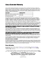
Graco warrants all equipment referenced in this document which is manufactured by Graco and bearing its
name to be free from defects in material and workmanship on the date of sale to the original purchaser for use.
With the exception of any special, extended, or limited warranty published by Graco, Graco will, for a period of
twelve months from the date of sale, repair or replace any part of the equipment determined by Graco to be
defective. This warranty applies only when the equipment is installed, operated and maintained in accordance
with Graco’s written recommendations.

Description

Description

Description

Warranty

Warranty

Warranty Period

Period

Period

Gear train, chassis, and electric motor

36 Months

Electronics cover and all other

e-Xtreme Driver parts

12 Months

This warranty does not cover, and Graco shall not be liable for general wear and tear, or any malfunction,
damage or wear caused by faulty installation, misapplication, abrasion, corrosion, inadequate or improper
maintenance, negligence, accident, tampering, or substitution of non-Graco component parts. Nor shall Graco
be liable for malfunction, damage or wear caused by the incompatibility of Graco equipment with structures,
accessories, equipment or materials not supplied by Graco, or the improper design, manufacture, installation,
operation or maintenance of structures, accessories, equipment or materials not supplied by Graco.

This warranty is conditioned upon the prepaid return of the equipment claimed to be defective to an authorized
Graco distributor for verification of the claimed defect. If the claimed defect is verified, Graco will repair or replace

free of charge any defective parts. The equipment will be returned to the original purchaser transportation
prepaid. If inspection of the equipment does not disclose any defect in material or workmanship, repairs will be
made at a reasonable charge, which charges may include the costs of parts, labor, and transportation.

THIS

THIS

THIS WARRANTY

WARRANTY

WARRANTY IS

IS

IS EXCLUSIVE,

EXCLUSIVE,

EXCLUSIVE, AND

AND

AND IS

IS

IS IN

IN

IN LIEU

LIEU

LIEU OF

OF

OF ANY

ANY

ANY OTHER

OTHER

OTHER WARRANTIES,

WARRANTIES,

WARRANTIES, EXPRESS

EXPRESS

EXPRESS OR

OR

OR IMPLIED,

IMPLIED,

IMPLIED,

INCLUDING

INCLUDING

INCLUDING BUT

BUT

BUT NOT

NOT

NOT LIMITED

LIMITED

LIMITED TO

TO

TO WARRANTY

WARRANTY

WARRANTY OF

OF

OF MERCHANTABILITY

MERCHANTABILITY

MERCHANTABILITY OR

OR

OR WARRANTY

WARRANTY

WARRANTY OF

OF

OF FITNESS

FITNESS

FITNESS

FOR

FOR

FOR A

A

A PARTICULAR

PARTICULAR

PARTICULAR PURPOSE

PURPOSE

PURPOSE.

Graco’s sole obligation and buyer’s sole remedy for any breach of warranty shall be as set forth above. The
buyer agrees that no other remedy (including, but not limited to, incidental or consequential damages for lost
profits, lost sales, injury to person or property, or any other incidental or consequential loss) shall be available.
Any action for breach of warranty hereunder must be brought within the latter of two (2) years of the date of sale,
or one (1) year after the warranty period expires.

GRACO

GRACO

GRACO MAKES

MAKES

MAKES NO

NO

NO WARRANTY,

WARRANTY,

WARRANTY, AND

AND

AND DISCLAIMS

DISCLAIMS

DISCLAIMS ALL

ALL

ALL IMPLIED

IMPLIED

IMPLIED WARRANTIES

WARRANTIES

WARRANTIES OF

OF

OF MERCHANTABILITY

MERCHANTABILITY

MERCHANTABILITY

AND

AND

AND FITNESS

FITNESS

FITNESS FOR

FOR

FOR A

A

A PARTICULAR

PARTICULAR

PARTICULAR PURPOSE,

PURPOSE,

PURPOSE, IN

IN

IN CONNECTION

CONNECTION

CONNECTION WITH

WITH

WITH ACCESSORIES,

ACCESSORIES,

ACCESSORIES, EQUIPMENT,

EQUIPMENT,

EQUIPMENT,

MATERIALS

MATERIALS

MATERIALS OR

OR

OR COMPONENTS

COMPONENTS

COMPONENTS SOLD

SOLD

SOLD BUT

BUT

BUT NOT

NOT

NOT MANUFACTURED

MANUFACTURED

MANUFACTURED BY

BY

BY GRACO.

GRACO.

GRACO. These items sold, but not

manufactured by Graco (such as electric motors, switches, hose, etc.), are subject to the warranty, if any, of
their manufacturer. Graco will provide purchaser with reasonable assistance in making any claim for breach of

these warranties.

In no event will Graco be liable for indirect, incidental, special or consequential damages resulting from Graco
supplying equipment hereunder, or the furnishing, performance, or use of any products or other goods sold
hereto, whether due to a breach of contract, breach of warranty, the negligence of Graco, or otherwise.

FOR

FOR

FOR GRACO

GRACO

GRACO CANADA

CANADA

CANADA CUSTOMERS

CUSTOMERS

CUSTOMERS

The Parties acknowledge that they have required that the present document, as well as all documents, notices

and legal proceedings entered into, given or instituted pursuant hereto or relating directly or indirectly hereto, be
drawn up in English. Les parties reconnaissent avoir convenu que la rédaction du présente document sera en
Anglais, ainsi que tous documents, avis et procédures judiciaires exécutés, donnés ou intentés, à la suite de ou
en rapport, directement ou indirectement, avec les procédures concernées.

Graco

Graco

Graco Information

Information

Information

For the latest information about Graco products, visit

www.graco.com.

For patent information, see

www.graco.com/patents.

To

To

To place

place

place an

an

an order,

order,

order, contact your Graco Distributor or call to identify the nearest distributor. Phone:

Phone:

Phone: 612-623-6921 or

or

or Toll

Toll

Toll Free:

Free:

Free:

1-800-328-0211 Fax:

Fax:

Fax: 612-378-3505

All written and visual data contained in this document reflects the latest product information available at the time of publication.

Graco reserves the right to make changes at any time without notice. Original Instructions. This manual contains English. MM 3A5124

3A5124

3A5124

Graco

Graco

Graco Headquarters:

Headquarters:

Headquarters: Minneapolis International

International

International Offices:

Offices:

Offices: Belgium, China, Japan, Korea

GRACO

GRACO

GRACO INC.

INC.

INC. AND

AND

AND SUBSIDIARIES

SUBSIDIARIES

SUBSIDIARIES ••• P.O.

P.O.

P.O. BOX

BOX

BOX 1441

1441

1441 ••• MINNEAPOLIS

MINNEAPOLIS

MINNEAPOLIS MN

MN

MN 55440-1441

55440-1441

55440-1441 ••• USA

USA

USA

Copyright

Copyright

Copyright 2016,

2016,

2016, Graco

Graco

Graco Inc.

Inc.

Inc. All

All

All Graco

Graco

Graco manufacturing

manufacturing

manufacturing locations

locations

locations are

are

are registered

registered

registered to

to

to ISO

ISO

ISO 9001.

9001.

9001.

www.graco.com

Revision B– May 2019

Содержание e-Xtreme Driver

Страница 1: ...rotective protective coatings coatings coatings using using using e e e Xtreme Xtreme Xtreme Sprayers Sprayers Sprayers For For For professional professional professional use use use only only only Important Important Important Safety Safety Safety Instructions Instructions Instructions Read all warnings and instructions in this manual and the system manual Save all instructions See pages 3 for mo...

Страница 2: ... Driver Assembly 24X901 22 Repair Kits and Accessories 24 Mounting Hole Pattern 25 Wiring Schematic 26 Technical Specifications 27 Graco Extended Warranty 28 Model Model Model Information Information Information Driver Driver Driver Model Model Model Part Part Part Series Series Series Description Description Description 24X901 A e Xtreme Driver 2575 2575 2575 II 2 G Ex db IIA T4 5 C Ta 50 C FM15A...

Страница 3: ...not plug or unplug power cords or turn power or light switches on or off when flammable fumes are present Use only grounded hoses Hold gun firmly to side of grounded pail when triggering into pail Do not use pail liners unless they are anti static or conductive Stop Stop Stop operation operation operation immediately immediately immediately if static sparking occurs or you feel a shock Do not use ...

Страница 4: ...ds or covers removed Pressurized equipment can start without warning Before checking moving or servicing equipment follow the Pressure Pressure Pressure Relief Relief Relief Procedure Procedure Procedure and disconnect all power sources SKIN SKIN SKIN INJECTION INJECTION INJECTION HAZARD HAZARD HAZARD High pressure fluid from dispensing device hose leaks or ruptured components will pierce skin Thi...

Страница 5: ...ponent See Technical Technical Technical Specifications Specifications Specifications in all equipment manuals Use fluids and solvents that are compatible with equipment wetted parts See Technical Technical Technical Specifications Specifications Specifications in all equipment manuals Read fluid and solvent manufacturer s warnings For complete information about your material request Safety Data S...

Страница 6: ...essure Control Knob P Oil Fill Cap vented S Power Switch Lock out tag out equipped Y Electrical Junction Box X Conduit Entry Z Electrical Junction Box Cover ZZ Ground Screws The driver requires a dedicated circuit protected by a circuit breaker or fused safety switch See Driver Installation manual for details The driver ships pre filled with oil from the factory The temporary unvented cap is for s...

Страница 7: ...eplaced with the supplied vented oil cap P before use PX P ti31010a Grounding Grounding Grounding This equipment must be grounded to reduce the risk of static sparking and electric shock Electric or static sparking can cause fumes to ignite or explode Improper grounding can cause electric shock Grounding provides an escape wire for the electric current Driver Driver Driver The driver is grounded t...

Страница 8: ...elief Relief Procedure Procedure Procedure Follow the Pressure Relief Procedure whenever you see this symbol This equipment stays pressurized until pressure is manually relieved To help prevent serious injury from moving parts or pressurized fluid such as skin injection follow the Pressure Relief Procedure when you stop spraying and before cleaning checking or servicing the equipment 1 Turn the po...

Страница 9: ...r under the oil drain port Remove the oil drain plug G Allow all oil to drain from the driver 2 Reinstall the oil drain plug G Torque to 18 23 ft lb 25 30 N m NOTICE NOTICE NOTICE Do not over torque The drain plug can become stripped and damaged 3 Open the fill cap P and add Graco Part No 16W645 Silicone Free Synthetic ISO 220 EP Gear Oil Check the oil level in the sight glass K Fill until the oil...

Страница 10: ... Type Troubleshooting Troubleshooting Troubleshooting Steps Steps Steps 1 Alarm Pump Pump Pump diving diving diving The pump is diving rapidly A pressure imbalance between the up and down stroke of the pump is causing the pump to dive with excessive speed Pump diving may occur when the pump runs out material while spraying at high pressure Verify that material is being properly fed to the pump Pre...

Страница 11: ...Verify that the encoder cable EE is connected securely see Wiring Schematic page 26 The encoder may need replacement See Graco Graco Graco Contact Contact Contact Information Information Information Graco Extended Warranty page 28 10 Alarm Software Software Software Versions Versions Versions Do Do Do Not Not Not Match Match Match See the system manual for software token part number Obtain softwar...

Страница 12: ...lass 12 9 steel or better with a minimum yield strength of 1100 MPa 160 000 psi are acceptable alternatives Replace Replace Replace Output Output Output Seal Seal Seal Cartridge Cartridge Cartridge 1 Stop the pump at the bottom of its stroke Shut off and lock out power to the driver 2 Follow the Pressure Relief Procedure page 8 3 Disconnect the lower from the driver as explained in your separate s...

Страница 13: ...r Light L for the status of the software update a The Status Indicator Light will blink slowly for a few seconds and then rapidly for several seconds b Once the update is complete the unit will power up and flash out the software version Three numbers will be flashed out to convey the software version in the format of x yy zzz For example flash pause flash flash pause flash pause would indicate th...

Страница 14: ...ench 15 ft lb 20 N m Prepare Prepare Prepare Driver Driver Driver 1 Remove power from the driver Follow appropriate lock out tag out procedures Wait five minutes before servicing 2 Follow the Pressure Relief Procedure page 8 3 Decouple the pump lower from the driver per the system manual Disconnect Disconnect Disconnect Power Power Power Wires Wires Wires 1 Remove the screws J and junction box cov...

Страница 15: ...s Ensure all connectors are securely attached to the control board See Wiring Schematic page 26 2 Secure loose motor wires into the clip inside the housing see Wiring Schematic page 26 3 Reinstall electronics cover onto center housing 4 Install the 12 bolts using a 6 mm hex wrench NOTE NOTE NOTE Ensure the lock washers are still in place 5 Torque the bolts to 15 ft lb 20 N m Power Power Power Unit...

Страница 16: ...e Prepare Prepare Driver Driver Driver 1 Remove power from the driver Follow appropriate lock out tag out procedures Wait five minutes before servicing 2 Follow the Pressure Relief Procedure page 8 3 Decouple the pump lower from the driver per the system manual Remove Remove Remove Electronics Electronics Electronics Cover Cover Cover When When When Also Also Also Replacing Replacing Replacing the...

Страница 17: ...head mounting screws AD Rotor Bearing Housing Install Install Install New New New Encoder Encoder Encoder 1 If replacing the encoder cable AE AF also place the encoder connector cable through the motor housing NOTE NOTE NOTE The encoder connector AE end is the smaller of the two connectors AE Encoder connector smaller AF Control board connector larger 2 Slide the new encoder onto the rotor shaft 3...

Страница 18: ...e 26 2 Secure loose motor wires into the clip inside the housing see Wiring Schematic page 26 3 Reinstall electronics cover onto center housing 4 Install the 12 bolts using a 6 mm hex wrench NOTE NOTE NOTE Ensure the lock washers are still in place 5 Torque the bolts to 15 ft lb 20 N m Reinstall Reinstall Reinstall Motor Motor Motor Cover Cover Cover 1 Reinstall motor cover onto driver housing 2 I...

Страница 19: ...r 1 Remove power from the driver Follow appropriate lock out tag out procedures Wait five minutes before servicing 2 Follow the Pressure Relief Procedure page 8 3 Decouple the pump lower from the driver per the system manual Remove Remove Remove Electronics Electronics Electronics Cover Cover Cover NOTICE NOTICE NOTICE To avoid equipment damage carefully support the cover when removing the last bo...

Страница 20: ... tighten the position sensor Damage to the position sensor may result 3 Tighten the jam nut on the position sensor finger tight NOTICE NOTICE NOTICE Do not use a wrench to tighten the jam nut Damage to the position sensor may result 4 Plug the position sensor into the control board see Wiring Schematic page 26 5 Reset the dip switch Reinstall Reinstall Reinstall Electronics Electronics Electronics...

Страница 21: ...Notes Notes Notes Notes 3A5124B 21 ...

Страница 22: ...Parts Parts Parts Parts Driver Driver Driver Assembly Assembly Assembly 24X901 24X901 24X901 22 3A5124B ...

Страница 23: ...46 25C170 SCREW shcs M8 x 1 25 80 mm 4 pack 4 49 17M815 KIT fan bearing with coupler 1 49a COUPLER 1 49b 25C182 KIT seal input shaft 1 49c 119539 RING retaining internal 1 51 25C181 BRACKET shroud mount 1 51a 120668 SCREW flat head M5X 8 1 53 25C183 KIT fan 1 53a 122347 RING retaining external 1 55 25C184 KIT cover shroud 1 55a 124165 SCREW shcs M5 0 8 x 10 ss 1 100 15H392 ADAPTER rod Xtreme 1 106...

Страница 24: ...6W645 Silicone Free Synthetic ISO 220 EP Gear Oil 1 quart 0 95 liter order 2 24W120 Position Sensor see Position Sensor Replacement page 19 25C169 Encoder see Encoder Replacement page 16 25C187 Control board see Control Board Replacement 25C187 page 14 e Xtreme Driver Software Update Kit see system manual 24X901 Connection kits to mount an e Xtreme Driver to an existing pump lower Kits include tie...

Страница 25: ...le Hole Pattern Pattern Pattern A A A 6 186 in 157 mm B B B 6 186 in 157 mm C C C Four 3 8 16 Mounting Holes D D D Six 5 8 11 Tie Rod Holes 8 in 203 mm x 120 bolt circle OR 5 9 in 150 mm x 120 bolt circle E E E 15 6 in 395 mm F F F 15 75 in 400 mm 3A5124B 25 ...

Страница 26: ...c Schematic Schematic AA AA AA Install Motor Connector Under Clip BB BB BB Motor Temp Cable CC CC CC Motor Power Cable DD DD DD Token Cable EE EE EE Encoder Cable FF FF FF Position Sensor and Cable GG GG GG J7 J7 J7 Reed Switch not used 26 3A5124B ...

Страница 27: ...mum force 4 200 lbf 18 7 kN Power inlet port size 3 4 14 npt f Ambient temperature range 25 120 F 5 50 C Oil capacity 1 0 1 2 quarts 0 9 1 1 liters Oil specification Graco Part No 16W645 Silicone Free Synthetic ISO 220 EP Gear Oil Weight 110 lb 50 kg Minimum recommended generator size 5 kW Sound Emissions per ISO 9614 for Normal Operation 20 cpm Sound Pressure LpA Average 70 2 dBA Sound Power LwA ...

Страница 28: ...of sale or one 1 year after the warranty period expires GRACO GRACO GRACO MAKES MAKES MAKES NO NO NO WARRANTY WARRANTY WARRANTY AND AND AND DISCLAIMS DISCLAIMS DISCLAIMS ALL ALL ALL IMPLIED IMPLIED IMPLIED WARRANTIES WARRANTIES WARRANTIES OF OF OF MERCHANTABILITY MERCHANTABILITY MERCHANTABILITY AND AND AND FITNESS FITNESS FITNESS FOR FOR FOR A A A PARTICULAR PARTICULAR PARTICULAR PURPOSE PURPOSE P...

Отзывы: