background image

Important Two-Component Material Information

Important Two-Component Material Information

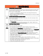
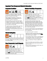
Isocyanate Conditions

Spraying or dispensing materials containing

isocyanates creates potentially harmful mists,

vapors, and atomized particulates.
Read material manufacturer’s warnings and

material MSDS to know specific hazards and

precautions related to isocyanates.
Prevent inhalation of isocyanate mists, vapors,

and atomized particulates by providing sufficient

ventilation in the work area. If sufficient ventilation

is not available, a supplied-air respirator is required

for everyone in the work area.
To prevent contact with isocyanates, appropriate

personal protective equipment, including

chemically impermeable gloves, boots, aprons,

and goggles, is also required for everyone in the

work area.

Material Self-Ignition

Some materials may become self-igniting if applied

too thickly. Read material manufacturer’s warnings

and material MSDS.

Keep Components A and B Separate

Cross-contamination can result in cured

material in fluid lines which could cause serious

injury or damage equipment. To prevent

cross-contamination of the equipment’s wetted

parts, never interchange component A (isocyanate)

and component B (resin) parts.

Moisture Sensitivity of Isocyanates

Cross-contamination can result in cured

material in fluid lines which could cause serious

injury or damage equipment. To prevent

cross-contamination of the equipment’s wetted

parts, never interchange component A (isocyanate)

and component B (resin) parts.

Isocyanates (ISO) are catalysts used in two

component foam and polyurea coatings. ISO will

react with moisture (such as humidity) to form small,

hard, abrasive crystals, which become suspended in

the fluid. Eventually a film will form on the surface

and the ISO will begin to gel, increasing in viscosity. If

used, this partially cured ISO will reduce performance

and the life of all wetted parts.
The amount of film formation and rate of crystallization

varies depending on the blend of ISO, the humidity,

and the temperature.
To prevent exposing ISO to moisture:
• Always use a sealed container with a desiccant

dryer in the vent, or a nitrogen atmosphere. Never

store ISO in an open container.

• Keep the ISO lube pump reservoir (if installed) filled

with appropriate lubricant. The lubricant creates a

barrier between the ISO and the atmosphere.

• Use only moisture-proof hoses compatible with

ISO.

• Never use reclaimed solvents, which may contain

moisture. Always keep solvent containers closed

when not in use.

• Always lubricate threaded parts with ISO pump oil

or grease when reassembling.

3A1705E

7

Содержание 259079

Страница 1: ...With Integrated Generator For spraying polyurethane foam and polyurea coatings For professional use only Not approved for use in explosive atmospheres or hazardous locations Important Safety Instructi...

Страница 2: ...e Check Hose 41 Connect Remote Display Module 41 Grounding 41 Supply Wet Cups With Throat Seal Liquid TSL 42 Advanced Display Module ADM Operation 43 Advanced Setup Screens 46 System 47 Recipes 47 Run...

Страница 3: ...electrician and comply with all local codes and regulations TOXIC FLUID OR FUMES Toxic uids or fumes can cause serious injury or death if splashed in the eyes or on skin inhaled or swallowed Read MSDS...

Страница 4: ...is running or hot shut off engine and let it cool Fuel is ammable and can ignite or explode if spilled on hot surface Eliminate all ignition sources such as pilot lights cigarettes portable electric...

Страница 5: ...us injury Do not operate the unit when fatigued or under the in uence of drugs or alcohol Do not exceed the maximum working pressure or temperature rating of the lowest rated system component See Tech...

Страница 6: ...er metal objects Only use tools with insulated handles Do not lay tools or metal parts on top of battery MOVING PARTS HAZARD Moving parts can pinch cut or amputate ngers and other body parts Keep clea...

Страница 7: ...and component B resin parts Moisture Sensitivity of Isocyanates Cross contamination can result in cured material in uid lines which could cause serious injury or damage equipment To prevent cross cont...

Страница 8: ...d in your equipment requires special attention to avoid equipment damage and downtime When changing materials ush the equipment multiple times to ensure it is thoroughly clean Always clean the uid inl...

Страница 9: ...rking Pressure psi MPa bar 259081 32 Amps 240 V 1 11 700 2 0 7 6 0 0203 0 0771 3500 24 1 241 259091 12 Amps 240 V 1 16 700 2 0 7 6 0 0203 0 0771 3500 24 1 241 Total system watts used by system based o...

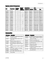
Страница 10: ...246101 AP9180 259080 24K394 246050 Fusion AP 246101 AP9181 259081 24K395 246055 Fusion AP 246100 CS9079 259079 24K240 246050 Fusion CS CS0101 CS9080 259080 24K240 246050 Fusion CS CS0101 CS9081 25908...

Страница 11: ...2R1 P29091 259091 24K241 246055 Probler P2 GCP2R0 P29189 259089 24K394 246050 Probler P2 GCP2R1 P29190 259090 24K394 246050 Probler P2 GCP2R1 P29191 259091 24K395 246055 Probler P2 GCP2R0 Accessories...

Страница 12: ...ls in English System Manuals 3A1706 Reactor E 30i and E XP2i Repair Parts Displacement Pump Manual 309577 Electric Reactor Displacement Pump Repair Parts Feed System Manuals 309572 Heated Hose Instruc...

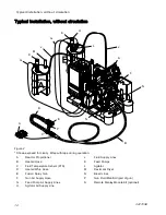
Страница 13: ...e during operation A Reactor Proportioner B Heated Hose C Fluid Temperature Sensor FTS D Heated Whip Hose E Fusion Spray Gun F Gun Air Supply Hose G Feed Pump Air Supply Lines H Agitator Air Supply Li...

Страница 14: ...tape during operation A Reactor Proportioner B Heated Hose C Fluid Temperature Sensor FTS D Heated Whip Hose E Fusion Spray Gun F Gun Air Supply Hose G Feed Pump Air Supply Lines H Agitator Air Suppl...

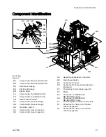
Страница 15: ...Manifold GA Component A Pressure Gauge GB Component B Pressure Gauge GG Generator page 17 HA Component A Hose Connection HB Component B Hose Connection HC Heated Hose Electrical Connectors MP Main Po...

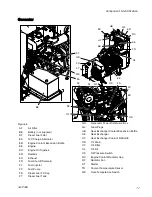
Страница 16: ...ncluded with all models FV Fluid Inlet Valve A side shown HE Heat Exchangers heat exchanger coolant loop HM High Power Temperature Control Module HPTCM Cable Connections page 26 LM Low Power Module LP...

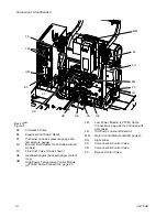
Страница 17: ...l Dipstick ER Radiator EX Exhaust FD Fuel Shutoff Solenoid FJ Fuel Injector FP Fuel Pump FS Diesel Fuel Fill Cap FT Diesel Fuel Tank GD Generator Power Distribution Box GL Glow Plugs HB Heat Exchanger...

Страница 18: ...r PL Component B Feed Pump and Agitator Air Regulator PM Gun Air Regulator PN Component A Feed Pump Pressure Gauge PP Component B Feed Pump and Agitator Pressure Gauge PR Gun Pressure Gauge Not for br...

Страница 19: ...lays system status C Stop Stops all system processes Is not a safety or emergency stop D Soft Keys Selects the speci c screen or operation shown on the display directly next to each key Call out Butto...

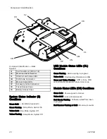
Страница 20: ...System On Green Flashing Setup Mode System On Yellow Solid Run Mode System Off Yellow Flashing Setup Mode System Off USB Module Status LEDs CL Conditions Green Flashing Data recording in progress Yel...

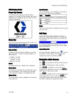
Страница 21: ...u bar There are four possibilities Icon Function No Icon No information or no error has occurred Advisory Deviation Alarm Status The current system status is displayed at the lower right of the menu b...

Страница 22: ...information Softkeys Icon Function Start Proportioner Start and Stop Proportioner in Jog Mode Stop Proportioner Turn on speci ed heat zone Park component A pump Enter Jog Mode See Jog Mode page 60 Re...

Страница 23: ...s 2 Heat Exchanger Control Vave Output to load center 3 Two way Splitter to A and B Heat Exchanger Temperature Sensors 5 Engine Coolant Temperature Sensor 6 Pump Cycle Switch 7 Optional Accessory Conn...

Страница 24: ...see Appendix A Engine Control Module page 90 Figure 11 Engine Control Module Icon Description Function On Start Engine Auto Auto mode not used Off Stop all system processes Is not a safety or emergenc...

Страница 25: ...enoid FS Green Fuel shutoff solenoid on the engine is open D2 Starter ST Red Starter is cranking D3 Glow Plugs GL Green Glow plugs are heating D4 Radiator Fan RF Green Radiator fan is on D10 A Coolant...

Страница 26: ...ections 7 Rotary Switch Token Access 8 Module Status LEDs see Advanced Display Module ADM page 19 CN for conditions Low Power Module LPTCM Cable Connections Only used with E XP2i and E 30i models with...

Страница 27: ...ings listed in the following tables S HPTCM Rotary Switch Location Figure 16 S LPTCM Rotary Switch Location Figure 17 HPTCM A and B Rotary Switch Settings Setting Zone 0 Heated Hose 1 Not Used 2 Not U...

Страница 28: ...Cabinet Fan Power Supply and Coolant Circulation Pump CB04 30 A Auxiliary Power Air Compressor CB05 10 A Auxiliary Power CB06 20 A Auxiliary Power E XP2i and E 30i With Heat Low Power Temperature Con...

Страница 29: ...optional circuit breakers and their current ratings Circuit breakers used must meet UL489 speci cations Auxiliary Wiring Diagram Options The generator supplies power in a 3 wire single phase mid point...

Страница 30: ...on the ADM PD The engine coolant loop gray circulates heated coolant from the engine EE through the heat exchanger HE radiator ER and back to the engine Coolant in the proportioner coolant loop black...

Страница 31: ...ed in the proportioner pumps PA PB After the A and B material has been heated in the heat exchangers the material enters the uid manifold FM and heated hose For models with a booster heater the A and...

Страница 32: ...lose the A and B material has reached target temperature Coolant ows through the bypass control valve VC circulation pump CP sight glass SG proportioner coolant ll bottle HF and back to the heat excha...

Страница 33: ...d Connect air line A2 between proportioner air inlet to air dryer outlet e Connect pilot air lines A3 and A4 between the air compressor and air tank f Secure water drain lines A5 and A6 to the frame...

Страница 34: ...Setup A5 A1 A2 AS AN A3 AT A3 A4 A2 A6 A4 34 3A1705E...

Страница 35: ...the diameter of the exhaust pipe Metal or other approved reproo ng materials that provides at least 8 in 203 mm of insulation between the exhaust pipe and ammable material Exhaust pipes not covered a...

Страница 36: ...of the pallet and place where the fuel ll spout is easily accessible Note Do not mount fuel tank in front of the generator air intake or where it will limit opening and access to the electrical enclos...

Страница 37: ...Setup 1 25 in 31 75 mm IW 1 25 in 31 75 mm 15 in 381 mm 6 in min 406 4 mm 1 ft min 0 3m Wall IW Installation Guidelines Figure 27 3A1705E 37...

Страница 38: ...t bypass the fusible link when damaged The fusible link prevents damage to other system components See the system repair manual for repair instructions Figure 29 3 Cover battery terminals with plastic...

Страница 39: ...A drum and use desiccant dryer M in vent 3 Install agitator L in component B drum if necessary 4 Connect supply hoses from feed pumps to the component A and component B material inlets on the system...

Страница 40: ...18 3 m minimum NOTICE Apply grease on all system and hose uid ttings This lubricates the threads and prevents material from hardening on the threads 1 Turn main power switch OFF 2 Assemble heated hose...

Страница 41: ...bolt and braided cable from pallet Install grounding cable terminated with a ring terminal cable and terminal not supplied under braided cable Reinstall bolt and torque to minimum 25 ft lbs 34 N m An...

Страница 42: ...SO Pump Keep reservoir R lled with Graco Throat Seal Liquid TSL Part 206995 Wet cup piston circulates TSL through wet cup to carry away isocyanate lm on displacement rod R Component A Pump Figure 33 C...

Страница 43: ...19 If the System Status Indicator Light is not green press the ADM Power On Off A button The System Status Indicator Light will illuminate yellow if the machine is disabled Perform the following task...

Страница 44: ...password then press Press to navigate through the Setup Mode screens See Setup Screens Navigation Diagram page 45 Set Password Set a password to allow Setup screen access see Advanced Screen 1 General...

Страница 45: ...Advanced Display Module ADM Operation Setup Screens Navigation Diagram Figure 35 3A1705E 45...

Страница 46: ...at current date time setup screens password 0000 for none or 0001 to 9999 screen saver delay and enable or disable silent mode Advanced Screen 2 Units Use this screen to set the temperature units pres...

Страница 47: ...able saved recipes Enabled recipes can be selected at the Home Run Screen 24 recipes can displayed on the three recipe screens Add Recipe 1 Press and then use to select a recipe eld Press to enter a r...

Страница 48: ...eration Run Mode The ADM will start in the Run screens at the Home screen Press to navigate through the Run Mode screens See Run Screens Navigation Diagram page 44 From the Run screens press to access...

Страница 49: ...Advanced Display Module ADM Operation Run Screens Navigation Diagram Figure 36 3A1705E 49...

Страница 50: ...park the component A pump enter jog mode and clear cycles Home System With Error Active errors are shown in the status bar The error code alarm bell and description of the error will scroll in the sta...

Страница 51: ...All information listed on this screen can be downloaded on a USB ash drive Events This screen shows the date time event code and description of all events that have occurred on the system There are 1...

Страница 52: ...hemical Hose Chemical Booster A Chemical Booster B Chemical Booster A PCB temperature control module temperature Booster B PCB temperature control module temperature Hose PCB temperature control modul...

Страница 53: ...ooting screen for an error code that is not listed on this screen See Error Codes and Troubleshooting page 74 for more information on error codes Recipes Use this screen to select an enabled recipe Us...

Страница 54: ...at Off B E B D H Heat Off Hose E B P X Pump Off E B R X Jog Off E B U X USB Drive Removed E C 0 X Setup Value Changed E C D A A Temperature Setpoint Changed E C D B B Temperature Setpoint Changed E C...

Страница 55: ...ns Before daily startup ensure that the uid inlet screens are clean See Flush Inlet Strainer Screen page 67 4 Check ISO lubrication reservoir Check level and condition of ISO lube daily See Pump Lubri...

Страница 56: ...has been relieved b Press start on the air compressor power box CB Wait until the pressure gauge CJ on the air supply tank reaches 30 psi c Open the desiccant dryer inlet valve water drain valve and...

Страница 57: ...hot uid or equipment Do not turn on hose heat without uid in hoses Allow equipment to cool completely before touching it Wear gloves if uid temperature exceeds 110 F 43 C Thermal expansion can cause...

Страница 58: ...S cables SC at the Reactor Fluid Manifold FM SC B 15V837 A 2 Insert the RTD sensor probe between the two hoses where the scuff guard ends 3 Lower the hose temperature setpoint on the system ADM screen...

Страница 59: ...chine is operating 2 See Typical Installation with circulation page 13 Route circulation lines back to respective component A or B supply drum Use hoses rated at the maximum working pressure of this e...

Страница 60: ...Use hoses rated at the maximum working pressure of this equipment See Technical Speci cations page 98 3 Follow procedures from Startup page 55 4 Turn main power switch on 5 Set temperature targets Se...

Страница 61: ...ratures are on target see Home screen page 50 7 Verify that the engine temperature is at least up to the minimum operation temperature range The fan will start running when the engine has reached maxi...

Страница 62: ...esults in an uneven pattern coarse droplet size low ow and poor mixing Too much pressure results in excessive overspray high ow rates dif cult control and excessive wear Fluid temperature Similar effe...

Страница 63: ...the system 6 Turn off the air compressor air dryer and breathing air 7 Close the main air shutoff valve 8 Turn main power switch OFF To prevent electric shock do not remove any shrouds or open the el...

Страница 64: ...and before cleaning checking or servicing equipment The Fusion AP gun is shown 1 Relieve pressure in gun and perform gun shutdown procedure See gun manual 2 Close gun uid inlet valves A and B 3 Shut o...

Страница 65: ...ible with common solvents Use only moisture free solvents To ush feed hoses pumps and heaters separately from heated hoses set PRESSURE RELIEF SPRAY valves SA SB to PRESSURE RELIEF CIRCULATION Flush t...

Страница 66: ...cation System page 68 Compressor Tank Water Drain Open the manual water drain valve weekly See valve location on page 34 Open only when air pressure is less than 25 psi Dust Protection Use clean dry o...

Страница 67: ...e at the pump inlet and shut off the appropriate feed pump This prevents material from being pumped while cleaning the screen 2 Place a container under the strainer base to catch drain off when removi...

Страница 68: ...operation If the packings are operating properly lubricant replacement due to discoloration should not be necessary more often than every 3 or 4 weeks To change pump lubricant 1 Follow Pressure Relie...

Страница 69: ...d B heat exchanger control valves and bypass control valve Note The battery must be connected to operate valves The load center LC LEDs will stay on when the manual valve switch MV is in the ON positi...

Страница 70: ...air enters the coolant system It takes about one full warm up and cool down cycle to purge air from coolant To avoid burns do not perform maintenance on the coolant system until the coolant system has...

Страница 71: ...y use coolant solutions that are compatible with the system See Coolant Speci cations page 71 1 Perform Shutdown page 63 2 Remove the engine radiator coolant cap RC and ll until the coolant reaches th...

Страница 72: ...play as well as by the light tower optional Alarms are indicated by This condition indicates a parameter critical to the process has reached a level requiring the system to stop The alarm needs to be...

Страница 73: ...Note Press or to return to the previously displayed screen 2 Press to select one of following conditions that are present in the system until you are able to diagnose the error Press to return to the...

Страница 74: ...og and displayed on the Error and Troubleshooting screens on the ADM Error Code Error Location Type Name Cause Solution Loose or bad connection Check wiring between MCM and motor Motor brushes complet...

Страница 75: ...he support frame of the transformer Short circuit of motor wiring Check wiring to the motor to ensure no bare wires are touching and that no wires are shorted to ground Motor will not rotate Replace m...

Страница 76: ...module should be lit If green light is not lit check to make sure each CAN cable connection is tight Verify the power supply is outputting 24 Vdc If not replace power supply See System Repair manual C...

Страница 77: ...le switch and MCM port 6 F9DX MCM ALARM Pressure Flow Cutback Mix chamber is too large for the set pressure Reference the pressure ow curves and select a tip size that is the correct size for the set...

Страница 78: ...on the pumps Bad pressure transducer Verify the ADM pressure reading the analog gauges at the manifold Replace transducers if they do not match P4BX MCM ALARM Over Pressure B E XP2i system con gured a...

Страница 79: ...unnecessary alarms and abort dispenses Out of material Fill tanks with material P7AX Pressure Imbalance A High P7BX MCM ALARM Pressure Imbalance B High Feed system defective Check feed pump and hoses...

Страница 80: ...ter board See system repair manual If voltage is present measure the resistance of the coil it should be 12 5 if coil is open replace coil If voltage is present test the coil with screwdriver The scre...

Страница 81: ...stics in Reactor repair manual T4CA Boost A LPTCM Over Temperature Cooling fan not operating on power If fan is not working check wiring between CB03 and fan If wiring is good replace fan T4CB Boost B...

Страница 82: ...lugged radiator Replace if needed Cooling fans are not operating properly Ensure ambient temperature is less than 120 F 48 C Check to see that the fans are moving Measure voltage to fans There should...

Страница 83: ...nnection to check and retighten any loose connector Measure hose RTD cable and FTS continuity See system repair manual Order RTD Test Kit 24N365 for measurement See Temporary Manual Hose Temperature C...

Страница 84: ...ires Low generator line voltage Measure voltage across main power switch CT01 Voltage should measure between 190 and 264 VAC V1MH Hose ALARM Low Line Voltage High auxiliary inrush current Ensure compr...

Страница 85: ...the lights on USB port stop ashing before Removing the token WSUX USB ADVISORY USB Invalid Con guration Bad ADM Replace ADM See System Repair manual WXUD ADM ADVISORY USB Download Error Log Download...

Страница 86: ...vent code Event code Event type Action taken Event Description Event codes include both error codes alarms deviations and advisories and record only events Actions Taken includes setting and clearing...

Страница 87: ...te log was created Time log was created Component name Software version loaded on the above component Blackbox Log File The black box le name is 5 BLACKB CSV and is stored in the DATAxxxx folder The B...

Страница 88: ...load Procedure page 89 to install the le The format of the custom language le is critical The following rules must be followed in order for the installation process to succeed De ne a custom string fo...

Страница 89: ...roper folder structure on the USB ash drive 2 Insert USB ash drive into USB port of computer 3 The USB ash drive window automatically opens If it does not open USB ash drive from within Windows Explor...

Страница 90: ...tery voltage Press to scroll through the run screens Press to enter the Information screens Run Screen Layout Inst Icon Alarm Icon Instrumentation Units Mode Icon Information Screens From the Run Scre...

Страница 91: ...Manual Engine is at rest and the unit is in manual run mode Timer animation Engine is starting up Running animation Engine is running Instrumentation Icons A small icon is displayed in the instrument...

Страница 92: ...top the generator Clear the alarm and remove the fault Then press the stop button to reset the module See the information screen to see the latest alarm Icon Description Details Fail To Start The engi...

Страница 93: ...Dimensions Dimensions Top View Figure 43 Side View Figure 44 3A1705E 93...

Страница 94: ...Dimensions Top View System with Compressor and Hose Rack Accessories Figure 45 Front View Figure 46 Side View System with Compressor and Hose Rack Accessories Figure 47 94 3A1705E...

Страница 95: ...Dimensions Pallet Mounting Dimensions Figure 48 3A1705E 95...

Страница 96: ...6060 03 AR7070 04 AR5252 02 AR4242 01 2000 138 1500 103 1000 69 500 34 0 5 2 3 15 6 8 20 9 1 25 11 3 30 13 6 35 15 9 45 20 4 40 18 1 55 25 9 50 22 7 10 4 5 E 30i PRESSURE psi bar FLOW lbs min kg min P...

Страница 97: ...Notes Notes 3A1705E 97...

Страница 98: ...gal 0 1034 liter Operating Ambient Temperature Range Temperature 20 to 120 F 7 to 49 C Auxiliary Power Available Voltage 120 Vac or 240 Vac 60 Hz Engine Model Perkins 404 22G 2 2 L 29 HP Alternator M...

Страница 99: ...0 MPa 103 bar 2 gpm 7 6 lpm 91 0 dBA Fluid Inlets Component A ISO and Component B RES 3 4 NPT f with 3 4 NPSM f union Fluid Outlets Component A ISO 8 1 2 in JIC with 5 5 16 in JIC adapter Component B...

Страница 100: ...perating Ambient Temperature Range Temperature 20 to 120 F 7 to 49 C Auxiliary Power Available Voltage 120 Vac or 240 Vac 60 Hz Engine Model Perkins 404 22G 2 2 L 29 HP Alternator Model Mecc Alte 22 k...

Страница 101: ...essure measured from 3 1 ft 1 m at 2000 psi 14 MPa 138 bar 1 0 gpm 3 8 lpm 91 0 dBA Fluid Inlets Component A ISO and Component B RES 3 4 NPT f with 3 4 NPSM f union Fluid Outlets Component A ISO 8 1 2...

Страница 102: ...es for lost pro ts lost sales injury to person or property or any other incidental or consequential loss shall be available Any action for breach of warranty must be brought within two 2 years of the...

Отзывы: