


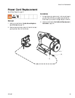

Control Board Replacement
18
311990F
Control Board Replacement
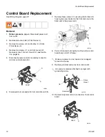
See Wiring Diagram, page 27.
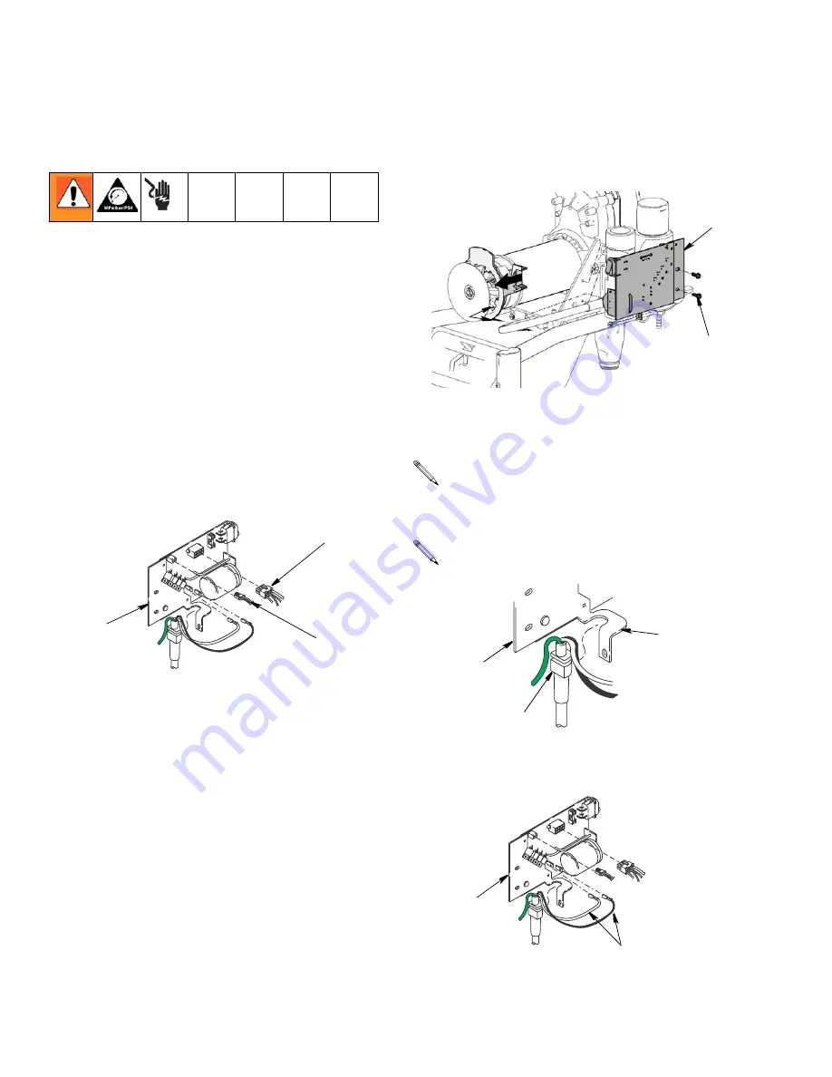
Removal
1.
Relieve pressure
, page 6. Disconnect power cord
from outlet.
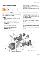
2.
Remove kick stand (66) (210
ES
Series A).
3.
Remove two screws (5) and toolbox (3) (190
ES
,
210
ES
Series A).
4.
Remove two screws (11) and front cover (32).
Remove screw (13) and shroud (12) (see illustra-
tion, page15).
5.
Disconnect pressure control assembly connector
(A) from control board (18).
6.
Disconnect motor connector (D) from control board (18).
7.
Remove three screws (11) securing control board to
housing (two are located on the front and one on the
back next to the power cord).
8.
Pull control board out slightly and then slide control
board back and off of frame.
9.
Remove grommet and wires from strain relief.
.
10. Remove two power cord (C) connectors from control
board.
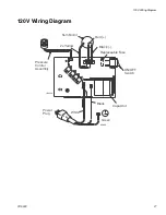
120V
ti9132a
18
D
A
Make sure power cord is free and not wrapped
around cord wrap.
Ground wire remains attached to sprayer with
grounding screw.
11
18
ti9154a
ti6122a
18
Grommet
Strain
Relief
120V
C
ti9132a
18