pg. 5
Step 1: Leg Assembly
Parts Needed:
-Frame Leg (3)
-Table Support (4)
-Table Angle Support (4)
-M6 x 16mm SBHCS (8)
-M6 x 10mm Connector Bolt (8)
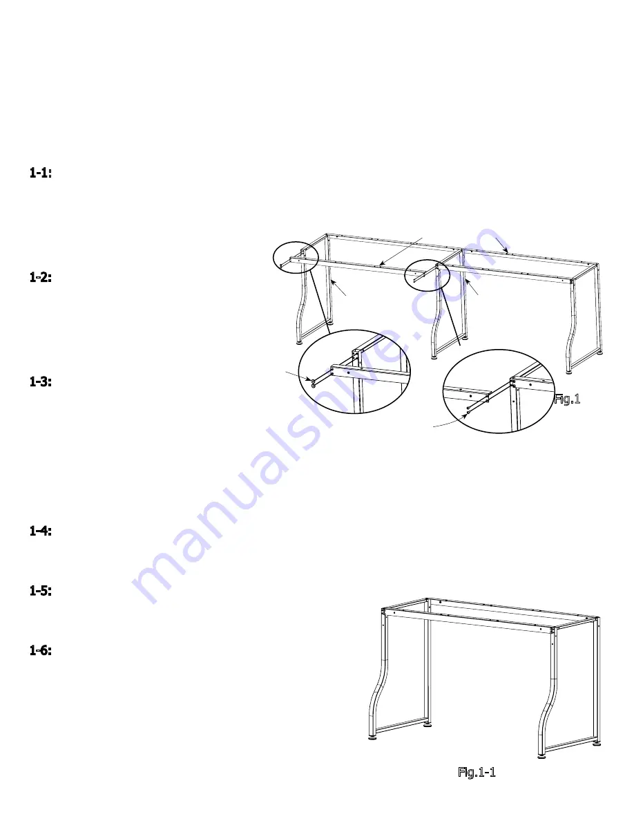
1-1: Set up the Frame Leg on the left side.
Place Table Support on top of the curved tube
of the leg. Line up the holes on the table
support with the right row of holes on the
leg. Screw a M6 x 10mm Connector
Bolt into each hole, as shown in Fig. 1
1-2: Place a Table Support on
top of the back side of the Frame Leg.
Line up the holes the same way
as the previous table support. Screw
a M6 x 10mm Connector Bolt into
each hole, as shown in Fig. 1
1-3: Place a Frame Leg at the
end of the table supports,
making sure the curved tube is facing the same
direction as the left side Frame Leg. Line up the left row
of holes with the table supports and screw in the M6 x 16mm
SBHCS, as shown in Fig.1. Make sure the legs line up well, and the table supports are parallel.
Note: For assembling the crib size frame, please line up the screw holes on table supports with the left
row of holes on the middle leg, and lock them with M6x10mm Connector Bolts, as shown in Fig. 1-1.
1-4: On the front side of the frame, place a Table Support on to the top of the middle Frame Leg, line up
the holes on the table support with the other row of holes on the leg. Screw an M6 x 10mm Connector
Bolt into each hole, as shown in Fig. 1.
1-5: Place a Table Support on to the top of the back side of
the Middle Frame Leg. Line up the holes and screw a
M6 x 10mm Connector Bolt into each hole, as shown in Fig.1.
1-6:
Place the right Frame Leg at the end of the unfixed table
supports, oriented the the same direction as the left and
middle Frame Legs. Line up the right row of holes on the leg
with the holes on the table supports, Screw a M6 x 10mm
Connector Bolt into each hole, as shown in Fig.1.
Frame
Front
Frame Back
(2) M6 x 10mm
Connector Bolt
(2) M6 x 16mm
SBHCS
Frame Leg
Frame Leg
Table Support 1
Fig.1
Fig.1-1
Содержание SR2+
Страница 19: ...pg 19 ...


