


02.11.2018
1
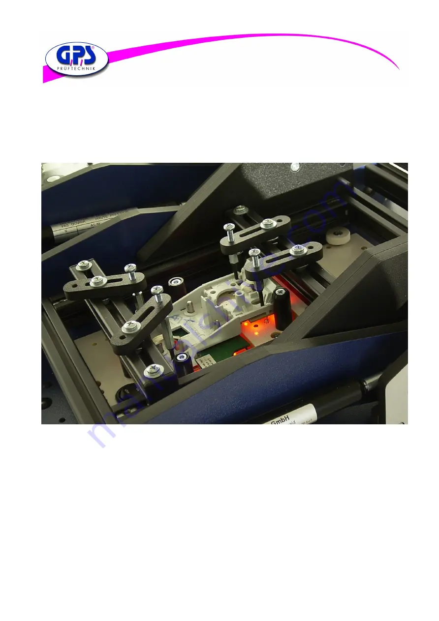
User Manual for Digital Colour Analyzer
GPS Prueftechnik GmbH
www.gps-prueftechnik.de
E-Mail: [email protected]
02.11.2018
1
User Manual for Digital Colour Analyzer
GPS Prueftechnik GmbH
www.gps-prueftechnik.de
E-Mail: [email protected]


