


3
in the area a bolt-on or child-proof cover is
recommended.
3. PIPING
3.1. Discharge pipe should be the same size
as the pump discharge to insure optimum
performance. Using undersized pipe may
dramatically reduce the flow and therefore
waste energy. Your pump supplier can sug-
gest the correct pipe for your installation.
3.2. Install a threaded pipe adapter, matched
to the pipe type you are using, into the
threaded pump discharge. One end will have
a male thread and the other end will have
a barbed connector, compression fitting or
solvent weld connector. Use Teflon
®
tape on
all threaded joints. If using solvent welded
pipe and fittings it is best to dry fit them first
and after verifying the fit, solvent weld. A
union installed just above the sump or basin
cover will facilitate future maintenance and
replacement. See Chart 1 for discharge sizes.
3.3. Install a line check valve within 2 feet of
the pump. Install per valve manufacturer’s
instructions.
IMPORTANT - Drill a
1
⁄
8
" (3.2mm) relief hole
in the discharge line approximately 2” (51
mm) above the pump discharge connection
but below the check valve and within the
sump. This “relief ” hole allows trapped air
to escape from the pump and prevents air-
locking the pump. Failure to drill this hole
is a major cause of sump pumps failing to
pump after long periods of inactivity such as
seasonal use. Model ST is self-venting - no
hole is required.
4. INSTALLATION IN SUMP
4.1. The pump can be placed directly on the
bottom of a poly or fiberglass sump basin
or a concrete sump bottom. If the bottom is
packed gravel the stones must be larger than
½” (13mm) in diameter and the pump
should be placed on bricks for support.
4.2. After connecting the discharge pipe to the
pump it can be lowered into the sump (ba-
sin). Always lower the pump by the handle
and the pipe, never by the power cord. Place
the pump against the basin wall so the switch
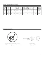
is to the center. See "Installation Data".
3. PIPING
4. INSTALLATION IN SUMP
1. GENERAL INFORMATION
1.1. Sump pumps are designed to operate inter-
mittently and usually seasonally. It is recom-
mended that you test the pump before your
rainy season begins to insure that the pump
and switch are operating properly.
1.2. We suggest installing a high water alarm
system and a battery back-up pump system
for finished basements or areas where flood-
ing will cause property damage. A back-up
generator is another option you can discuss
with your pump installer. Most power out-
ages occur during rain storms, just when
you need your sump pump the most! Pump
manufacturer's warranties cover only the
pump. Labor and incidental damage such as
flooding is not covered.
2. PRE-INSTALLATION CHECKS
2.1. Open all cartons and inspect for shipping
damage. Report any damage to your supplier
immediately.
2.2. Verify that all equipment is the correct volt-
age. Warranty does not cover damage caused
by connecting pumps and controls to incor-
rect voltage.
2.3. Is your basin sized correctly and the proper
type for the location?
Diameter - It must be wide enough to allow
the pump and switch to physically fit and
provide room for the switch to operate
freely. The vertical switch models typically
require less diameter than the wide-angle
float models. See "min. basin diameter" in
Chart 1.
Depth - It must be deeper
than the minimum depth at
which the switch turns the pump On. As an
example, if the pump turns on at 15" you
want to use a basin deeper than 15”.
See "On level" in Chart 1.
Style - There are several
sump basin styles available.
The location of the sump determines if you
require a cover and what type you require.
It is important to keep debris from entering
the sump and clogging the pump. An open
sump in a traffic area such as a basement is
dangerous. If children or pets will be playing
2. PRE-INSTALLATION CHECKS
1. GENERAL INFORMATION
WARNING
CAUTION