


8
ENGINEERING DATA
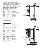
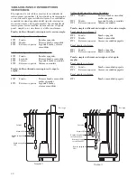
PUMP OPERATION
Figure 2
Double Float - Hard Wired
Figure 3
Determining Pumping Range
Figure 1
Pumpmaster and Pumpmaster Plus -
Hard Wired
Engineering data for specific models may be found in your catalog and on our website (address is on the cover).
Control panel wiring diagrams are shipped with the control panels. Please use the control panel drawings in conjunction with this instruction
manual to complete the wiring.
Minimum Submergence
Continuous
Duty
Fully Submerged
Intermittent
Duty
6” Below Top of Motor
Maximum Fluid Temperature
Continuous
Operation
104º F 40º C
Intermittent
Operation
140º F 60º C
6" (15.3 cm)
6" (15.3 cm)
8" (20.3 cm) TURN ON LEVEL
WEIGHT
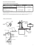
Single-Action Float Switch
“Typical” Installation
Figure 4
Pumping
range
Wide-Angle Float Switch
Piggyback
switch plug
Pump plug
Figure 5
Содержание SP035V
Страница 38: ...38 NOTES NOTAS ...
Страница 39: ...39 NOTES NOTAS ...