NT-Evolution 2.0 Installation Guide
2
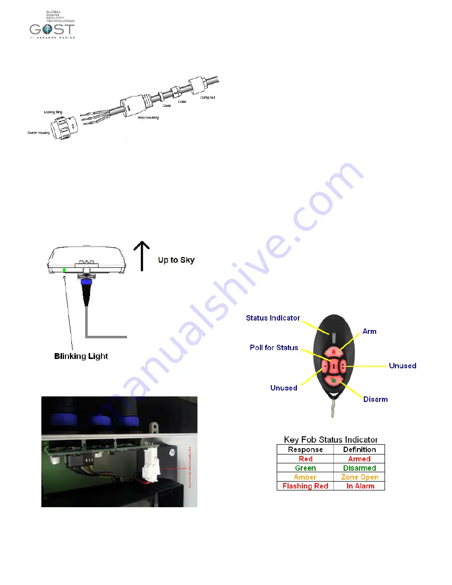
Figure 4
3.) Mount the control unit according to the Control Unit Locations suggested.
Allow for a service loop near control unit connections for possible
accessibility later.
4.) Connect the power cable to a constant +12VDC or +24VDC and
–
Negative Ground. Then plug it into the control unit.
5.) Connect Antenna connection to the antenna.
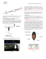
6.) There is a light at the base of the antenna Figure 5... Assure that the
antenna is rotated to a position where the light is visible to the installer. When
the unit is first powered up it will initially blink red, then gradually change to
orange, and then green. The antenna should be blinking green within about
five minutes of startup. If it does not, confirm that the signal is not getting
blocked and adheres to the location considerations.
Figure 5
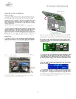
7.) Open up the cover of the control unit and Plug in the Battery Backup
Cable making sure that it is locked in place. Figure 6.
Figure 6
8.) Leave the antenna plugged in. Direct the owner to the sticker at the
bottom of the included user guide to activate the antenna. Antennas that
remain unactivated for more than two weeks are automatically sent a disable
command. A re-enabled command can be sent, though immediate activation
is suggested after installation.
*Pre-Activation of the antenna is preferred whenever possible to simplify
install.
9.) The NT-Evolution is wirelessly compatible with any of our existing
wireless sensors. These sensors are preprogrammed to the system before
leaving the factory. See the list on page one that identifies the particular
sensors and outputs.
System Functionality
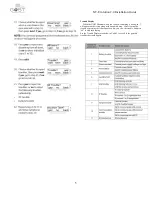
The primary means to control the NT-Evolution is thru the two key fob
remotes included with every system. These Key Fobs allow the User to
Arm/Disarm the system within 100ft of the vessel. Additionally, the user can
poll the unit for a status of the system such as Armed, Disarmed, Zone Open,
or In Alarm Figure 7.
*All buttons on the Key fob must be pressed for 1 second.
When the system is armed, a 500 meter (default) radius is placed around
your vessel called a
“geofence”. Should an armed vessel move outside this
geofence, the latitude, longitude, speed, and direction of the vessel will be sent
as an e-mail and/or text message to up to ten separate recipients every 15
minutes (default). Additionally, when the system is armed, should any of the
security sensors installed with the system trip, the system will go into alarm
and an
“alert” alarm will be sent to all the designated recipients. Many of
these alert and timing cycles of your system are programmable via message
commands from the website after activation. As an added feature, a
“Monitoring” Alert
will go out in the event that input voltage to the system is
cut or if the Vessels battery supply bank drops below 10 VDC, or if any of the
monitoring sensors are tripped regardless of the arm/disarm condition of the
system When Input voltage is restored to the proper level, an
“Alarm
Cleared
” warning is sent out.
Figure 7


