


SERVICING
33
S-101 LEAK TESTING
(NITROGEN OR NITROGEN-TRACED)
WARNING
WARNING
Pressure test the system using dry nitrogen and soapy water
to locate leaks. If you wish to use a leak detector, charge the
system to 10 psi using the appropriate refrigerant then use
nitrogen to finish charging the system to working pressure,
then apply the detector to suspect areas. If leaks are found,
repair them. After repair, repeat the pressure test. If no leaks
exist, proceed to system evacuation.
For a system that contains a refrigerant charge and is sus-
pected of having a leak, stop the operation and hold the explor-
ing tube of the detector as close to the tube as possible, check
all piping and fittings. If a leak is detected, do not attempt to
apply more brazing to the joint. Remove and capture the charge,
unbraze the joint, clean and rebraze.
For a system that has been newly repaired and does not con-
tain a charge, connect a cylinder of refrigerant, through a gauge
manifold, to the liquid and suction line dill valves and/or liquid
line dill valve and compressor process tube.
NOTE:
Refrigerant hoses must be equipped with dill valve de-
pressors or special adaptor used. Open the valve on the cylin-
der and manifold and allow the pressure to build up within the
system. Check for and handle leaks, as described above.
After the test has been completed, remove and capture the
leak test refrigerant.
S-102 EVACUATION
WARNING
This is the most important part of the entire service procedure.
The life and efficiency of the equipment is dependent upon the
thoroughness exercised by the serviceman when evacuating
air (non-condensable) and moisture from the system.
Air in a system causes high condensing temperature and pres-
sure, resulting in increased power input and reduced perfor-
mance.
Moisture chemically reacts with the refrigerant and oil to form
corrosive hydrofluoric and hydrochloric acids. These attack
motor windings and parts, causing breakdown.
The equipment required to thoroughly evacuate the system is
a high vacuum pump, capable of producing a vacuum equiva-
lent to 25 microns absolute and a thermocouple vacuum gauge
to give a true reading of the vacuum in the system
NOTE:
Never use the system compressor as a vacuum pump
or run when under a high vacuum. Motor damage could occur.
WARNING
SCROLL COMPRESSORS
DO NOT FRONT SEAT THE SERVICE VALVE(S) WITH
THE COMPRESSOR OPERATING IN AN ATTEMPT TO
SAVE REFRIGERANT. WITH THE SUCTION LINE OF
THE COMPRESSOR CLOSED OR SEVERLY RESTRICT-
ED, THE SCROLL COMPRESSOR WILL DRAW A DEEP
VACUUM VERY QUICKLY. THIS VACUUM CAN CAUSE
INTERNAL ARCING OF THE FUSITE RESULTING IN A
DAMAGED OR FAILED COMPRESSOR.
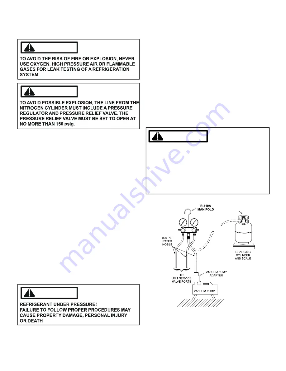
LOW SIDE
GAUGE
AND VALVE
HIGH SIDE
GAUGE
AND VALVE
1. Connect the vacuum pump, vacuum tight manifold set with
high vacuum hoses, thermocouple vacuum gauge and charg-
ing cylinder as shown.
2. Start the vacuum pump and open the shut off valve to the
high vacuum gauge manifold only. After the compound
gauge (low side) has dropped to approximately 29 inches
of vacuum, open the valve to the vacuum thermocouple


