background image

11

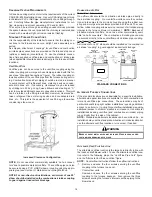
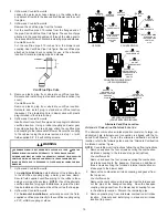
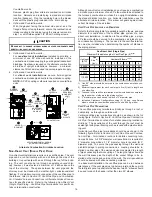
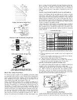
5. When directly communicating with the outdoors, the single open-

ing shall have a minimum free area of 1 square inch per 3,000
BTU per hour of total input rating of all equipment in the enclo-
sure.

5.3.4 Specially Engineered Installations:

The requirements of 5.3.3 shall not necessarily govern when special engi-

neering, approved by the authority having jurisdiction, provides an ad-
equate supply of air for combustion, ventilation, and dilution of flue
gases.

5.3.5 Louvers and Grilles:

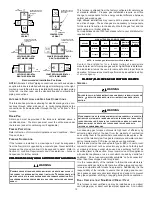
In calculating free area in 5.3.3, consideration shall be given to the block-

ing effect of louvers, grilles or screens protecting openings. Screens
used shall not be smaller than 1/4 inch mesh. If the area through a
design of louver or grille is known, it should be used in calculating the
size of opening required to provide the free area specified. If the design
and free area is not known, it may be assumed that wood louvers will
have 20-25 percent free area and metal louvers and grilles will have 60-
75 percent free area. Louvers and grilles shall be fixed in the open
position or interlocked with the equipment so that they are opened au-
tomatically during equipment operation.

5.3.6 Special Conditions Created by Mechanical Exhausting or Fire-

places:

Operation of exhaust fans, ventilation systems, clothes dryers, or fireplaces

may create conditions requiring special attention to avoid unsatisfac-
tory operation of installed gas utilization equipment.  Air from Inside
Building. See 5.3.3-a.

VI. INST

VI. INST

VI. INST

VI. INST

VI. INSTALL

ALL

ALL

ALL

ALLA

A

A

A

ATI

TI

TI

TI

TIO

O

O

O

ON POSITI

N POSITI

N POSITI

N POSITI

N POSITIO

O

O

O

ONS

NS

NS

NS

NS

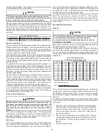
This furnace may be installed in an upright position or horizontal on
either the left or right side panel.  Do not install this furnace on its
back.  For 

upright upflow

 furnaces, return air ductwork may be at-

tached to the side panel(s) and/or basepan.  For 

horizontal upflow

furnaces, return air ductwork must be attached to the basepan.  For
both 

upright or horizontal counterflow

 furnaces, return ductwork must

be attached to the basepan (top end of the blower compartment).

NOTE:   

Ductwork must never be attached to the back of the fur-

nace.  Contact your distributor for proper airflow requirements and
number of required ductwork connections.  Refer to “Recommended
Installation Positions” figure for appropriate installation positions,
ductwork connections, and resulting airflow arrangements.

VII. HO

VII. HO

VII. HO

VII. HO

VII. HORIZO

RIZO

RIZO

RIZO

RIZONT

NT

NT

NT

NTAL APPLI

AL APPLI

AL APPLI

AL APPLI

AL APPLIC

C

C

C

CA

A

A

A

ATI

TI

TI

TI

TIO

O

O

O

ONS & CO

NS & CO

NS & CO

NS & CO

NS & CONSID

NSID

NSID

NSID

NSIDERA

ERA

ERA

ERA

ERATI

TI

TI

TI

TIO

O

O

O

ONS

NS

NS

NS

NS

G

ENERAL

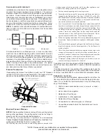
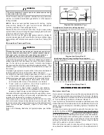
Horizontal applications, in particular, may dictate many of the
installation’s specifics such as airflow direction, ductwork connec-
tions, flue and combustion air pipe connections, etc.  The basic ap-
plication of this furnace as a horizontal furnace differs only slightly
from an upright installation.  When installing a furnace horizontally,
additional consideration must be given to the following:

ALTERNATE VENT/FLUE 

AND COMBUSTION AIR

INTAKE LOCATIONS

FURNACE MUST BE LEVEL

FROM END TO END

FURNACE MUST BE LEVEL

OR SLIGHTLY TILTED FORWARD

WITH THE DOORS 0" - 3/4" 

BELOW THE BACK PANEL

DRAIN LINE WITH 1/4" PER FOOT 

DOWNWARD SLOPE

36" MINIMUM SERVICE

CLEARANCE REQUIRED

FURNACE MUST BE SUPPORTED

AT BOTH ENDS AND MIDDLE

DRAIN PAN

GAS LINE WITH

DRIP LEG (3" MINIMUM)

4 3/4" MINIMUM

DRAIN TRAP

CLEARANCE

Horizontal Furnace

D

RAIN

 T

RAP


AND

 L

INES

In horizontal applications the condensate drain trap is secured to
the furnace side panel, suspending it below the furnace.  A mini-
mum clearance of 4 3/4 inches below the furnace must be provided
for the drain trap.  Additionally, the appropriate downward piping
slope must be maintained from the drain trap to the drain location.
Refer to 

Section X, Condensate Drain Trap and Lines

 for further

details. If the drain trap and drain line will be exposed to tempera-
tures near or below freezing, adequate measures must be taken to
prevent condensate from freezing.

L

EVELING

Leveling ensures proper condensate drainage from the heat ex-
changer and induced draft blower.  For proper flue pipe drainage,
the furnace must be level lengthwise from end to end.  The furnace
should also be level from back to front or have a slight tilt with the
access doors downhill (approximately 3/4 inches) from the back
panel.  The slight tilt allows the heat exchanger condensate, gener-
ated in the recuperator coil, to flow forward to the recuperator coil
front cover.

A

LTERNATE

 V

ENT

/F

LUE


AND

 C

OMBUSTION

 A

IR

 C

ONNECTIONS

In horizontal installations provisions for alternate flue and combus-
tion air piping are available for upflow furnaces with left discharge
and counterflow furnaces with right air discharge.  This configura-
tion allows the flue and combustion air piping to be run vertically
through the furnace.  Refer to the “Recommended Installation Posi-
tions” figure for further detail.  The standard piping connections may
also be used in these positions.  Refer to 

Section IX, Vent/Flue Pipe

and Combustion Air Pipe for details concerning the conversion to
the alternate vent/flue and combustion air connections.

Содержание GCS9

Страница 1: ...rself in a position which is more hazardous than when the unit is in operation Remember it is your responsibility to install the product safely and to know it well enough to be able to instruct a customer in its safe use Safety is a matter of common sense a matter of thinking before acting Most dealers have a list of specific good safety practices follow them The precautions listed in this Install...

Страница 2: ...ND JOINING METHODS 13 PROPER VENT FLUE AND COMBUSTION AIR PIPING PRACTICES 13 TERMINATION LOCATIONS 13 CANADIAN VENTING REQUIREMENTS 14 STANDARD FURNACE CONNECTIONS 14 ALTERNATE FURNACE CONNECTIONS 14 NON DIRECT VENT SINGLE PIPE PIPING 16 DIRECT VENT DUAL PIPE PIPING 17 VENT INTAKE TERMINATIONS FOR INSTALLATION OF MULTIPLE DIRECT VENT FURNACES 18 CONCENTRIC VENT TERMINATION 18 X Condensate Drain L...

Страница 3: ...tion 30 GENERAL 30 INTEGRATED CONTROL MODULE 30 PRIMARY LIMIT 30 AUXILIARY LIMIT 31 ROLLOUT LIMIT 31 PRESSURE SWITCHES 31 FLAME SENSOR 31 XVIII Troubleshooting 31 ELECTROSTATIC DISCHARGE ESD PRECAUTIONS 31 DIAGNOSTIC CHART 31 RESETTING FROM LOCKOUT 31 XIX Maintenance 31 ANNUAL INSPECTION 31 FILTERS 32 BURNERS 32 INDUCED DRAFT AND CIRCULATOR BLOWERS 32 CONDENSATE TRAP AND DRAIN SYSTEM QUALIFIED SER...

Страница 4: ...r warranty certificate is also supplied with the unit Read the warranty carefully and note what is covered Keep the warranty certificate in a safe location for future reference If additional information or operating instructions are required con tact the dealer where the purchase was made Homeowner Notice If the residence is left unattended for an extended period of time i e 4 hours or greater hav...

Страница 5: ...0 Coil Front Cover Drain Port 21 Drain Line Penetrations 22 Drain Trap 23 Blower Door Interlock Switch 24 Capacitor 25 Integrated Control Module with fuse and diagnostic LED 26 24 Volt Thermostat Connections 27 Transformer 40 VA 28 Circulator Blower 29 Auxiliary Limit 30 Junction Box 31 Electrical Connection Inlets 32 Coil Front Cover 33 Combustion Air Inlet Pipe Upflow Horizontal Counterflow Hori...

Страница 6: ...ughly read this manual for specifics pertaining to the installation and application of this product WARNING POSSIBLE PROPERTY DAMAGE PERSONAL INJURY OR DEATH DUE TO FIRE EXPLOSION SMOKE SOOT CONDENSTAION ELECTRICAL SHOCK OR CARBON MONOXIDE MAY RESULT FROM IMPROPER INSTALLATION REPAIR OPERATION OR MAINTENANCE OF THIS PRODUCT II SAFET II SAFET II SAFET II SAFET II SAFETY Y Y Y Y Please adhere to the...

Страница 7: ...ners fire horizontally into the heat exchanger Do not install the unit with the access doors on the up top or down bottom side of the furnace WARNING TO PREVENT PROPERTY DAMAGE PERSONAL INJURY OR DEATH DUE TO FIRE DO NOT INSTALL THIS FURNACE IN A MOBILE HOME TRAILER OR RECREATIONAL VEHICLE To ensure proper furnace operation install operate and maintain the furnace in accordance with these installa...

Страница 8: ...LITY Installations must adhere to the clearances to combustible materi als which this furnace has been design certified to The minimum clearance information for this furnace is provided on the unit s clear ance label These clearances must be permanently maintained Clearances must also accommodate an installation s gas electri cal and drain trap and drain line connections If the alternate com busti...

Страница 9: ...HIND DOORS IN CORNERS UNDER CABINETS Thermostat Influences Consult the instructions packaged with the thermostat for mounting instructions and further precautions V V V V V CO CO CO CO COMBUSTI MBUSTI MBUSTI MBUSTI MBUSTIO O O O ON VENTIL N VENTIL N VENTIL N VENTIL N VENTILA A A A ATI TI TI TI TIO O O O ON AIR REQUIREMENTS N AIR REQUIREMENTS N AIR REQUIREMENTS N AIR REQUIREMENTS N AIR REQUIREMENTS...

Страница 10: ... equip ment in the enclosure but not less than the sum of the areas of all vent connectors in the confined space Alternate Opening Location Equipment Located in Confined Spaces All Air from Outdoors Single Air Opening See 5 3 3 b Furnace Water Heater Opening Chimney or Gas Vent Opening NOTE Each opening must have a free area of not less than one square inch per 1000 BTU of the total input rating o...

Страница 11: ...L APPLI AL APPLI AL APPLI AL APPLIC C C C CA A A A ATI TI TI TI TIO O O O ONS CO NS CO NS CO NS CO NS CONSID NSID NSID NSID NSIDERA ERA ERA ERA ERATI TI TI TI TIO O O O ONS NS NS NS NS GENERAL Horizontal applications in particular may dictate many of the installation s specifics such as airflow direction ductwork connec tions flue and combustion air pipe connections etc The basic ap plication of t...

Страница 12: ...ce between natural and propane gas High altitude installations may require both a pressure switch and an orifice change These changes are necessary to compensate for the natural reduction in the density of both the gas fuel and the combustion air at higher altitude For installations above 7000 feet please refer to your distributor for required kit s Altitude Gas Kit Orifice Manifold Pressure Press...

Страница 13: ...AND EXCESSIVE HEAT AS THEY ARE COMBUSTIBLE LIQUIDS AVOID BREATHING CEMENT VAPORS OR CONTACT WITH SKIN AND OR EYES Two or three inch nominal diameter PVC Schedule 40 pipe meet ing ASTM D1785 PVC primer meeting ASTM F656 and PVC sol vent cement meeting ASTM D2564 specifications must be used Fittings must be DWV type fittings meeting ASTM D2665 and ASTM D3311 Carefully follow the manufacturer s instr...

Страница 14: ...NSTALLATIONS On upflow units secure the combustion air intake pipe directly to the air intake coupling On counterflow units secure the combus tion air intake pipe to the air intake coupling using the rubber cou pling and worm gear hose clamps provided with the unit The coun terflow rubber coupling allows service removal of air intake piping internal to the furnace blower compartment NOTE Because o...

Страница 15: ...d vent flue piping to the rubber elbow using a worm gear hose clamp NOTE Use of the alternate vent flue location for upright installations requires the drain trap be installed on the same side of the unit as the flue pipe 8 Upflow and Counterflow units For horizontal installations externally secure the field supplied vent flue pipe directly to the vent flue coupling using a PVC or ABS coupling or ...

Страница 16: ...e should be the wall thickness plus the depth of the socket fittings to be in stalled on the inside and outside of the wall The wall penetration should be sealed with silicone caulking material In a basement installation the vent flue pipe can be run between joist spaces If the vent pipe must go below a joist and then up into the last joist space to penetrate the header two 45 elbows should be use...

Страница 17: ... elbows and or tees in each Vent Flue Combustion Air Intake pipe Elbows and or tees used in the terminations must be included when determining the number of elbows in the piping systems If the combustion air intake pipe is to be installed above a finished ceiling or other area where dripping of condensate will be objection able insulation of the combustion air pipe may be required Use 1 2 thick cl...

Страница 18: ...op maintain the same minimum clearances be tween the exhaust vent and air intake terminations of adjacent units as with the exhaust vent and air intake terminations of a single unit If more than one direct vent furnace is to be installed horizontally through a common side wall maintain the clearances as in the fol lowing figure Always terminate all exhaust vent outlets at the same elevation and al...

Страница 19: ...LAMPS QTY 3 Hose and Tube Identification 1 Remove the rubber plug from the front cover drain port right or left side depending on the intended drain trap mounting 2 Secure HoseAto front cover drain port with a red hose clamp Route hose to rear side panel grommet hole NOTE For left side drainage grommets will have to be relocated to left side panel DRAIN TRAP FRONT COVER DRAIN PORT TUBE S 2 GREEN H...

Страница 20: ...over drain port and the rubber elbow drain port NOTE On counterflow models relocation of the front cover pressure switch hose is required Make connections as follows 1 Remove the rubber plug from the coil front cover drain port Counterflow furnaces Relocate the front cover pressure switch hose connection from the left side pressure tap to the right down side tap The pressure switch hose must be co...

Страница 21: ...Y PROPER OPERATION AFTER SERVICING WIRING HARNESS The wiring harness is an integral part of this furnace Field alter ation to comply with electrical codes should not be required Wires are color and number coded for identification purposes Refer to the wiring diagram for wire routings If any of the original wire as supplied with the furnace must be replaced it must be replaced with wiring material ...

Страница 22: ...AVOID INJURY ELECTRICAL SHOCK OR DEATH DISCONNECT ELECTRICAL POWER BEFORE SERVICING OR CHANGING ANY ELECTRICAL WIRING The furnace s integrated control module is equipped with line volt age accessory terminals for controlling power to an optional field supplied humidifier and or electronic air cleaner The accessory load specifications are as follows Humidifier 1 0 Amp maximum at 120 VAC Electronic ...

Страница 23: ... The appropriate manufacturer s propane gas conversion kit must be applied for pro pane gas installations Refer to the Section VIII Propane Gas High Altitude Installations section for details GAS VALVE This unit is equipped with a 24 volt gas valve controlled during fur nace operation by the integrated control module As shipped the valve is configured for natural gas The valve is field convertible...

Страница 24: ...OW MODEL MANUAL SHUT OFF VALVE UPSTREAM FROM GROUND JOINT PIPE UNION DRIP LEG GROMMET IN STANDARD GAS LINE HOLE DRAIN TRAP ALTERNATE GAS LINE LOCATION MANIFOLD PLUG IN ALTERNATE GAS LINE HOLE GAS VALVE GROUND JOINT PIPE UNION BURNERS GROMMET IN STANDARD GAS LINE HOLE COUNTERFLOW MANUAL SHUT OFF VALVE UPSTREAM FROM GROUND JOINT PIPE UNION ALTERNATE GAS LINE LOCATION PLUG IN ALTERNATE GAS LINE HOLE ...

Страница 25: ... joints to reduce noise transmission To prevent the blower from interfering with combustion air or draft when a central return is used a connecting duct must be installed between the unit and the utility room wall A room closet or alcove must not be used as a return air chamber When the furnace is used in connection with a cooling unit the fur nace should be installed in parallel with or on the up...

Страница 26: ... propane gas high altitude etc have been appropriately installed FURNACE STARTUP 1 Close the manual gas shutoff valve external to the furnace 2 Turn off the electrical power to the furnace the cooling unit to avoid condensation in the heating element With a parallel flow arrangement the dampers or other means used to control the flow of air must be adequate to prevent chilled air from entering the...

Страница 27: ...piping drip leg The supply pressure must be measured with the burners operating To measure the gas supply pressure use the following procedure OUTLET INLET Pressure Regulator Adjustment Under Cap Screw Gas Valve On Off Selector Switch Inlet Pressure Tap Side of Valve Outlet Manifold Pressure Tap White Rodgers Model 36F22 1 Turn OFF gas to furnace at the manual gas shutoff valve external to the fur...

Страница 28: ...GAS VALVE This valve is shipped from the factory with the regulator preset see control label Consult the appliance rating plate to ensure burner manifold pres sure is as specified If another outlet pressure is required follow these steps 1 Turn OFF all electrical power to the system 2 Using a 3 32 inch hex wrench loosen outlet pressure tap screw one turn Do not remove screw 3 Connect a calibrated ...

Страница 29: ...cable to your model provides an airflow table showing the relationship between airflow CFM and external static pressure E S P for the proper selection of heating and cooling speeds The cooling blower speed is shipped set on HIGH and the heating blower speed is set as indicated in the Product Data Book applicable to your model These blower speeds should be adjusted by the in staller to match the in...

Страница 30: ...from the burners without curling floating or lifting off Flames must not impinge on the sides of the heat exchanger firing tubes Check the burner flames for 1 Good adjustment 2 Stable soft and blue 3 Not curling floating or lifting off Burner Flame PRIMARY LIMIT The primary limit control guards against overheating resulting from insufficient conditioned air passing over the heat exchanger If the p...

Страница 31: ...fore removing a new control from its container Follow steps 1 through 3 if installing the control on a furnace Return any old or new controls to their containers before touching any ungrounded object DIAGNOSTIC CHART WARNING TO AVOID ELECTRICAL SHOCK INJURY OR DEATH DISCONNECT ELECTRICAL POWER BEFORE PERFORMING ANY SERVICE OR MAINTENANCE Refer to the Troubleshooting Chart at the end of this manual...

Страница 32: ...ME SENSOR QUALIFIED SERVICER ONLY Under some conditions the fuel or air supply can create a nearly invisible coating on the flame sensor This coating acts as an insu lator causing a drop in the flame sense signal If the flame sense signal drops too low the furnace will not sense flame and will lock out The flame sensor should be carefully cleaned by a qualified servicer using emery cloth or steel ...

Страница 33: ...rature packet near furnace X X X X XXII REP XII REP XII REP XII REP XII REPAIR REPL AIR REPL AIR REPL AIR REPL AIR REPLACEMENT PAR ACEMENT PAR ACEMENT PAR ACEMENT PAR ACEMENT PARTS TS TS TS TS When ordering any of the listed functional parts be sure to provide the furnace model manufacturing and serial numbers with the order Although only functional parts are shown in the parts list all sheet meta...

Страница 34: ...drain system Correct as necessary Correct pressure switch setpoint or contact motion Tighten or correct wiring connection Pressure switch hose blocked pinched or connected improperly Blocked flue and or inlet air pipe blocked drain system or weak induced draft blower Incorrect pressure switch setpoint or malfunctioning switch contacts Loose or improperly connected wiring Pressure switch circuit no...

Страница 35: ...FLASHES Flame sensor is coated oxidized Flame sensor incorrectly positioned in burner flame Lazy burner flame due to improper gas pressure or combustion air Induced draft blower runs continuously No furnace operation Integrated control module diagnostic LED is flashing FIVE 5 flashes Flame sensed with no call for heat Correct short at flame sensor or in flame sensor wiring Turn power OFF prior to ...

Страница 36: ...ED AND CONFORM TO N E C AND LOCAL CODES PK PINK 115 VAC HOT AND PARK TERMINALS LINE H FLAME SENSOR FRONT COVER PRESSURE SWITCH SINGLECONTROLON45KBTU NO C GY BK PLUG CONNECTION FIELD SPLICE SWITCH TEMP OR 24V THERMOSTAT CONNECTIONS BU GN GND 115 VAC 24 VAC BLOWER COMPARTMENT DOOR SWITCH OPEN WHEN DOOR OPEN DOOR SWITCH BK GND D IS C O N N EC T L N WH JUNCTION BOX 1 OR ID BLOWER PRESSURE SWITCH HEAT ...

Отзывы: