


11
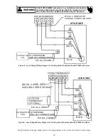
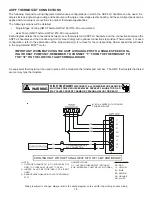
thermostat as shown in
Figures 10 and 11
.
Goodman® part number CHT18-60 is a single-stage cool and
single-stage heat thermostat.
Goodman® part number HPT18-60 is a single-stage cool,
two-stage heat pump thermostat. The first stage is heat pump
heating and the second stage is optional electric heat.
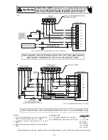
If additional features are desired, such as digital or program-
mable capabilities, these thermostats are commercially avail-
able. Follow the thermostat manufacturer’s instruction for in-
stallation.
Start-Up Procedure
•
Prior to start-up, ensure that all electrical connections
are properly sized and tightened.
•
All panels must be in place and secured. For Air Tight
application, neoprene gasket must be positioned at pre-
scribed locations to achieve 2% leakage.
•
Tubing must be leak free.
•
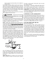
Unit should be elevated, trapped and pitched to allow
for drainage.
•
Low voltage wiring is connected.
•
Auxiliary drain is installed when necessary and pitched
to allow for drainage.
•
Drain pan and drain tubing has been leak checked.
•
Return and supply ducts are sealed.
•
Unit is elevated when installed in a garage or where
flammable vapors may be present.
•
Unit is protected from vehicular or other physical dam-
age.
•
Return air is not obtained from any areas where there
may be objectionable odors, flammable vapors or prod-
ucts of combustion such as carbon monoxide (CO),
which may cause serious personal injury or death.
Regular Maintenance
HIGH VOLTAGE!
Disconnect ALL power before servicing or
installing this unit. Multiple power sources may
be present. Failure to do so may cause property
damage, personal injury or death.
The only item to be maintained on a regular basis by the user
is the circulating air filter(s). Filter should be cleaned or re-
placed regularly. A certified service technician must perform
all other services.
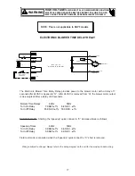
NOTE:
DO
NOT
USE THESE DIAGRAMS FOR AEPF
MODELS. SEE INSTALLATION AND OPERATING
INSTRUCTIONS SPECIFICALLY FOR AEPF MODELS.
0.1"
0.2"
0.3"
0.4"
0.5"
1
700
670
650
595
510
2
820
785
765
745
705
ASPF183016
3
920
900
850
840
815
4
1075
1055
1015
975
960
5
1130
1115
1085
1040
1000
1
1060
865
600
515
420
2
1105
910
795
745
690
ASPF303616
3
1165
1070
1020
960
915
4
1285
1240
1195
1140
1100
5
1435
1395
1350
1315
1265
1
1060
865
600
515
420
2
1105
910
795
745
690
ASPF313716
3
1165
1070
1020
960
915
4
1285
1240
1195
1140
1100
5
1435
1395
1350
1315
1265
1
1445
1275
1175
940
855
2
1545
1405
1325
1260
1145
ASPF426016
3
1660
1610
1555
1490
1415
4
1905
1870
1810
1750
1695
5
2115
2070
2000
1965
1915
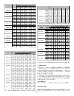
CFM deliverd against External Static Pressure
Model
Motor
Speed Tap
Table 13
Содержание ADPF
Страница 18: ...18 THIS PAGE LEFT INTENTIONALLY BLANK...
Страница 19: ...19 THIS PAGE LEFT INTENTIONALLY BLANK...


