background image

F870S 

4 Operation 

Page 19 

Gönnheimer Elektronic GmbH 

Tel.: +49 (6321) 49919-0 

Fax: +49 (6321) 49919-41 

4 Operation 

The user has total control of the purging system F870S by the use the joystick on the con-
trol unit FS870S respectively by using the external operating panel BT871. Operation on 
control unit FS870S panel BT871 is equal. Using the other operating panels only a restrict-
ed operation is possible. 

4.1 Human 

interface 

4.1.1 Display 

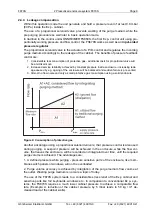
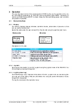
The built-in graphical display indicates operation modes, actual data of pressure or flow 
rate, as well as malfunctions. 
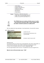
Beside the status side the user can switch to the info side using the joysticks right move. 
 

Status side 

Info side 


Purging

P = 0,8 mbar, Fl = 4 l/s


Description to Info- side: 
 

Row 

Description 

P = 2,0 mbar 

Actual pressure inside Ex p cabinet 

Q = 3,5 l/s   T = 20°C 

Flow rate through FS870S, air temperature 

Valve: 34% 

aperture rate of the input valve 

U = 65V   I = 162 mA 

Voltage and current at input valve (SVP) 

Throttle: 0,00 

Opening rate of the output valve 

Positive values : Throttle opens 
Negative values: Throttle gets tighter


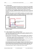
4.1.2 Joystick 

See process information to your Ex p system using the joystick inside of the FS870S. Con-
firm settings by pressing this joystick. 

4.1.3  Log file (show Log) 

The FS870S logs every important information of the Ex p system into an internal log file. 
The logs get a time stamp. With this information the user gets useful information if some-
thing works unexpected. 
The log file is located in the operation menu. 

P = 2,0 mbar 
Q = 3,5 l/s   T = 20°C 
Valve: 34% 
U = 65V   I = 162 mA 
Throttle: 0,00


Содержание F870S

Страница 1: ...User s manual Pressurized enclosure system F870S Manual_F870S_v1 0 2_2016 doc...

Страница 2: ...res in operation zone 21 Dust 12 2 6 1 Purging period cleaning period cleaning the housing inside 12 2 6 2 Additional marking 12 2 7 Additional information EC type certificate F850 SYST 12 2 8 Conform...

Страница 3: ...information Safety Measures to read and to comply Warning Extreme caution is advised when handling this device High electrical discharge is possible and can be fatal Work on electrical installations...

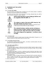
Страница 4: ...eration of this de vice should only be implemented by authorized persons and in strict accordance with local safe ty standards The electrical data on the type label and if applicable the special condi...

Страница 5: ...he enclosure 2 2 Pressurized enclosure according to EN 60079 Since the second issue of the standard EN 50016 May 1996 control devices for the pro tection type pressurized enclosure are classified as s...

Страница 6: ...introduction of proportional valve technology within pressurized enclosure systems patented system G nnheimer F850 an additional active proportional valve was integrated to the F870S in the outlet Fi...

Страница 7: ...e conventional systems are characterized by a fixed pressure flow curve see e g FS850S with an offset caused by the opening pressure of the passive mechanical outlet valve This typical opening pressur...

Страница 8: ...to any conventional Ex p system Within midrange flow rates the load to the Ex p cabinet walls is up to four times lower in comparison to conventional systems 2 4 Components of pressurized enclosure sy...

Страница 9: ...g leak age caused by e g ageing of the enclosure will be balanced and sudden failure is pre vented 3 Almost no flow noise and only a small protective gas consumption using a solid enclosure Figure 4 C...

Страница 10: ...agram 2 4 6 F870S Application using Containment Systems Containment Systems are defined as parts of a device within a pressurized enclosure which could emit combustible gas or occasionally an explosiv...

Страница 11: ...vantageous particularly when the control unit is mounted inside the enclosure 2 5 4 Common operating panels BT 854 1 and BT 855 1 On Off Switch Key operated switch for bypass LED indicator for READY...

Страница 12: ...ALL DUST FROM THE INSIDE OF THE ENCLOSURE BEFORE CONNECTING OR RESTORING THE ELECTRICAL SUPPLY On Ex p cabinets suitable for zone 21 which can be opened without tools has to be placed the following m...

Страница 13: ...purging 3 1 4 Particle barrier The control device contains a particle barrier according to EN 60079 2 Therefore it is al lowed to exhaust the purge medium direct onto the ex area 3 1 5 Proportional s...

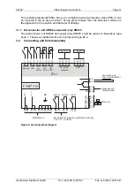
Страница 14: ...or unit SR852 and power relay SR853 could be placed in hazardous area Zone 1 These are certified on its own in protection type Ex e 3 2 Connecting and Commissioning 22 21 20 19 N L 36 37 34 35 24 26 2...

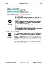
Страница 15: ...E 112 IECEx BVS 10 0095 and the regulative DIN EN 60079 14 Do not exceed terminal safety limits of each termi nal See limits in technical details or declarations of conformity The breaking current of...

Страница 16: ...ure sensor ES872 Ext configuration module CM873 11 FS870S 1 ext device 12 2 13 3 14 4 15 18 Port BT871 15 FS870S 1 BT871 16 2 17 3 18 4 3 2 4 Connections FS870S of protection class Ex e Clamps Descrip...

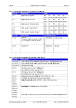
Страница 17: ...No Parameter Purge volume Purge volume 500 Ltr Set point of pressure controller while pre purging phase Setpoint Pres Purge 2 0 mbar Monitored minimum flow while pre purging phase Min Flow Purge 0 5...

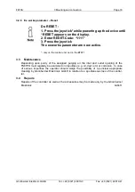
Страница 18: ...n the control unit not on the BT871 3 3 Maintenance Depending upon purity of the assigned purging air the inlet and outlet opening of the FS870S must regularly be examined on impurities e g oil dust e...

Страница 19: ...urging P 0 8 mbar Fl 4 l s Description to Info side Row Description P 2 0 mbar Actual pressure inside Ex p cabinet Q 3 5 l s T 20 C Flow rate through FS870S air temperature Valve 34 aperture rate of t...

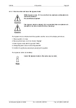
Страница 20: ...denied if it is possible that an explosive at mosphere can arise inside the Ex p housing The bypass can be activated with the joystick and the menu in the display as follows 1 Press joystick 2 x time...

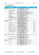
Страница 21: ...vice Inputs see actual status of the Ex i inputs c Exit menu 4 2 2 Parameter input menu Program the operation modes introduced above paragraph 2 within the setup menu of the FS870S Read in this paragr...

Страница 22: ...ans the solenoid valves and the ignition capa ble device inside the cabinet are switched off Find more details of the input parameter in List of parameters in the end of this manual 4 2 3 Menu exposit...

Страница 23: ...ailure Internal error on the output valve Send the unit back for maintenance Stepper motor wire break Internal error on the output valve Send the unit back for maintenance Stepper motor over current I...

Страница 24: ...VDC I 5 A P 150 W Pneumatics Pressure range 0 18 mbar Optional 0 350 mbar Flow range 0 10 ltr sec 0 36 m h at cabinet pressure 10 mbar hPa Extended measurement ranges on demand Ambient temperature 10...

Страница 25: ...sensor connector 0 1 Hardware Software version Standard Custom 0 x Solenoid valve SV Operation method digital proportional D P Effective diameter 2 mm 3 if SVP up to 300 ltr Ex p cabinet 5 if SVP more...

Страница 26: ...BT854 0 BT854 1 Operator panel in separate IP65 housing Without key operated switch With key operated switch Bypass BT855 0 BT855 1 Ex solenoid valve fuse Nominal Order Nr SVD x x 630 mA SI870 5 SVP x...

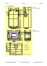
Страница 27: ...F870S 5 Annex Page 27 G nnheimer Elektronic GmbH Tel 49 6321 49919 0 Fax 49 6321 49919 41 5 4 Dimensions Figure 7 Dimensions FS870S Figure 8 Dimensions BT871...

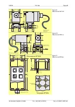
Страница 28: ...F870S 5 Annex Page 28 G nnheimer Elektronic GmbH Tel 49 6321 49919 0 Fax 49 6321 49919 41 Figure 9 Dimensions SVP 3 5 Figure 10 Dimensions SVD L x Figure 11 Dimensions BT85x x...

Страница 29: ...9 6321 49919 41 5 5 Mounting examples Figure 12 Mounting examples 5 6 Flow diagram The diagram shows the relationship between pressure inside of enclosure and the output flow The diagram is only valid...

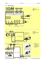
Страница 30: ...id v a l ve use Magnetventil Solenoid valv e 40 41 39 42 Ethernet 2 4 1 3 5 7 9 6 8 10 ext Alarm Bypass ON OK LED ON LED Ex i 12 16 14 18 11 15 13 17 ext Druck pressure BT871 BT871 Ext Sen Netz M ain...

Страница 31: ...origin package Disposal When the explosion proof multipurpose distribution switching and control units are eventually disposed of the national regulations governing the dis posal of waste materials i...

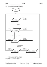
Страница 32: ...F870S 5 Annex Page 32 G nnheimer Elektronic GmbH Tel 49 6321 49919 0 Fax 49 6321 49919 41 5 9 Sequence of operation diagram Figure 16 Flow chart operation diagram...

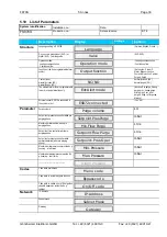
Страница 33: ...Inactive Pre purge During purge pre during purge After purge Pre after purge During after purge Always External sensor ES872 is connected to the system or not ES872 connected Yes No Parameter Purge vo...

Страница 34: ......

Страница 35: ......

Страница 36: ......

Страница 37: ......

Страница 38: ......

Страница 39: ......

Страница 40: ......

Страница 41: ......

Страница 42: ......

Страница 43: ......

Страница 44: ......

Страница 45: ......

Страница 46: ......

Страница 47: ......

Отзывы: