-
4-
PANEL DESCRIPTIONS
1.
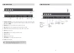
Input Selection Button:
Input 1~4 source selection (from the left to the right is input 1, input 2, input
3, and input 4). If you press the input 1 button about 5 seconds, the output layout will change to
Quad-view mode ( ).
2.
IR SENSOR:
IR sensor for receiving the IR commands from IR remote
3.
IR Receiver:
3.5mm socket for plugging in the extension cable of IR receiver
4.
Input 1-4:
HDMI inputs (from the left to the right is input 4, input 3, input 2, input 1)
5.
RS-232:
RS-232 control port
6.
Stereo Audio Out:
Connect to analog stereo audio speaker
7.
Output:
HDMI output
8.
Ethernet:
Ethernet control port
9.
Factory Reset:
Switch the pin to do factory default reset
10.
+12V DC:
12V DC power jack
For Quad-view mode, Upper left is Input 1; Rright upper is Input 2;
Lower left is Input 3; Right lower is Input 4.
!
-
5-
CONNECTION DIAGRAM


