6
IP G+
www.golmar.es
WEB CLIENT EL632/G+/48
- Double push buttons module panel:
Settings
Push buttons
Event log
About
10
20
30
9
19
29
132
131
8
18
28
7
17
27
6
16
26
5
15
25
4
14
24
3
13
23
2
12
22
1
11
21
Devices
Apply
010
020
030
009
019
029
132
131
008
018
028
007
017
027
006
016
026
005
015
025
004
014
024
003
013
023
002
012
022
001
011
021
PUSH BUTTONS
Next
Left
Right
Built-in push buttons
Reset
SIP servers
Single push button type
Settings
Push buttons
Event log
About
Devices
Apply
PUSH BUTTONS
Next
70
40
80
50
90
60
69
39
79
49
89
59
68
38
78
48
88
58
67
37
77
47
87
57
66
36
76
46
86
56
65
35
75
45
85
55
64
34
74
44
84
54
63
33
73
43
83
53
62
32
72
42
82
52
61
31
71
41
81
51
070
040
080
050
090
060
069
039
079
049
089
059
068
038
078
048
088
058
067
037
077
047
087
057
066
036
076
046
086
056
065
035
075
045
085
055
064
034
074
044
084
054
063
033
073
043
083
053
062
032
072
042
082
052
061
031
071
041
081
051
Previous
SIP servers
Settings
Push buttons
Event log
About
Devices
Apply
PUSH BUTTONS
130
100
110
120
129
99
109
119
128
98
108
118
127
97
107
117
126
96
106
116
125
95
105
115
124
94
104
114
123
93
103
113
122
92
102
112
121
91
101
111
130
100
110
120
129
099
109
119
128
098
108
118
127
097
107
117
126
096
106
116
125
095
105
115
124
094
104
114
123
093
103
113
122
092
102
112
121
091
101
111
Previous
SIP servers
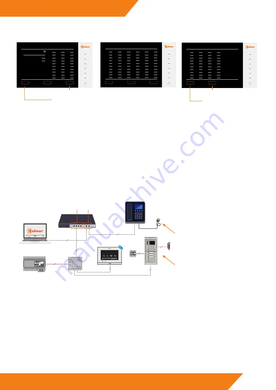
Go to the next screen.
Reset default settings.
Go to the previous screen.
Save changes set.
To modify the call addresses, we will assign the desired call address to every push button number in the same way as single push buttons
module panel.
3.3. Calls via SIP protocol
The system allows calls using VoIP telephones via the SIP protocol. There are two different ways to do it, adding the VoIP telephone
directly to the system or using a PABX telephone switchboard to act as a liaison between telephones and the system through extensions
that we will assign to the different devices of the system.
The following describes the two ways to make calls using the SIP protocol:
3.3.1. Add SIP device
In this section will show how to include a VoIP telephone with SIP protocol. In this case the call process is done directly. That is to say, the
system knows the VoIP telephone IP address and not an extension that it must ask to the switchboard.
Steps to follow:
1 - Connect the device to the system:
2
2
2
PRI 230V50/60HZ
SEC: 12V 6VA
12V
230V
TF-104
TF-104
D1
D2
IN
OUT
D3
D4
D4L-G+/PoE
+
-
18Vdc
Power
Columna
Riser
Local
D4L-G+/PoE
11:40
AM
20-02-2019
Wed
Door panel
Intercom
Recordings
Settings
FA-G+
UTP
UTP
UTP
12340100 FA-G+
UTP
SW-104
POE
UP-LINK
1
2
3
4
5-UP
6-UP
S
V
P
V
N
S
UP-LINK
PORTS
PORTS
SW-104
UTP
230V
POE
The used VoIP telephone is powered by 5Vdc.
Therefore, an Up-Link port has been used to receive only data
and to feed it locally with its power supply.
2 - SIP device IP address:
It will be necessary to know the device IP addres. Generally, VoIP telephones allow to show it on the telephone’s own display. If not, it is
possible to use programmes such as the one mentioned above “IP search Tool”.
If the device IP address is not in the same range as the system, it will be necessary to change it for one that is 10.XX.XX.XX. (remember
that the PC must be in the same range). See the process of modifying the phone manufacturer’s IP address.
Nexa panel with
EL632/G+ module.


