golden interstar Xpeed LAN 500 Скачать руководство пользователя страница 14


11 

Xpeed LAN 500

Chapter 3 – Configuration Utility Setup 

Introduction 

The Configuration Utility enables the users to identify HomePlug devices on the powerline 
network, measures data rate performance, ensures privacy and performs diagnostics by setting 
user defined secure powerline networks. 
The Utility will use a Graphical User Interface (GUI) with limited user selectable options.     
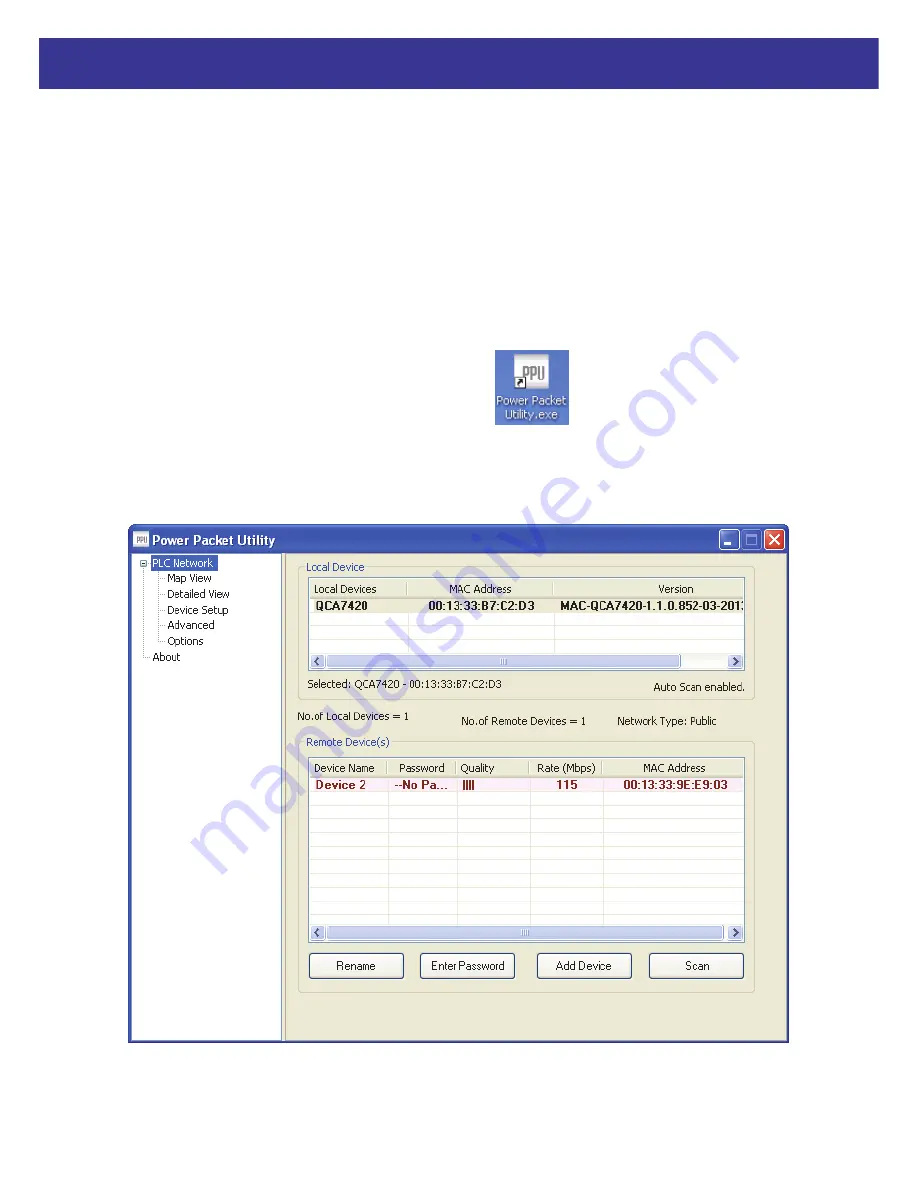
 

3.1 Map View 

In order to start the utility, double-click the utility icon 

  on desktop. Figure 3-1 shows 

the main screen of the Configuration Utility. The top panel of the screen shot shows a HomePlug 
AV device connected locally to the host computer. The bottom panel shows four devices 
connected remotely to the computer running the utility. 


Figure 3-1: Main Screen with HomePlug AV device Local 

Содержание Xpeed LAN 500

Страница 1: ...User s Manual...

Страница 2: ...its serviceable life this product should not be treated as household or general waste It should be handed over to the applicable collection point for the recycling of electrical and electronics equip...

Страница 3: ...2 2 1 Installing Powerline Device 2 2 2 Installation of Powerline Utility 3 2 3 Uninstallation of Configuration Utility 10 Chapter 3 Configuration Utility Setup 11 3 1 Map View 11 3 2 Detailed View 1...

Страница 4: ...MHz 68 MHz Security 128 bits AES encryption IEEE802 3 10Base T IEEE802 3U 100Base TX 1 3 LED Indicators The Powerline Ethernet Adaptor has three LEDs indicator Turn on when connected to AC power supp...

Страница 5: ...ed RJ45 Ethernet cable from your xDSL Cable Modem s Ethernet port to the Xpeed LAN 500 s LAN Ports 2 Connect the Xpeed LAN 500 to your wall mounted power outlet 3 Check if the PLC LED of Xpeed LAN 500...

Страница 6: ...is document are generated from Windows XP screen shots for Windows 7 Vista and Windows 8 will be similar 1 In order to install insert Configuration Utility CD ROM into the computer s CD ROM drive The...

Страница 7: ...4 Xpeed LAN 500 3 Please click Power line Utility button to continue 4 Click Next button to continue...

Страница 8: ...5 Xpeed LAN 500 5 Click I Agree button to continue 6 Click Install button to continue...

Страница 9: ...6 Xpeed LAN 500 7 Click Finish button to continue 8 Click Next button to continue...

Страница 10: ...7 Xpeed LAN 500 9 Click I Agree and then click Next button to continue 10 Click Next button to continue...

Страница 11: ...8 Xpeed LAN 500 11 Click Next button to continue 12 Click Close button to exit...

Страница 12: ...click the utility icon on desktop 14 You can see your device working well The top panel of the screen shot shows a Homeplug device connected locally to your computer The bottom panel shows one device...

Страница 13: ...uninstall the Configuration Utility go to the Control Panel of your system 2 Open the Add Remove Programs 3 Select and double click on the Powerline Utility in the Add Remove Programs Properties 4 Fol...

Страница 14: ...orks The Utility will use a Graphical User Interface GUI with limited user selectable options 3 1 Map View In order to start the utility double click the utility icon on desktop Figure 3 1 shows the m...

Страница 15: ...can select the local device by clicking on it and then click the Connect button to its right The status area above RESET NET ID button indicates that your PC is connected to that same device Once con...

Страница 16: ...ices associated with the currently selected local device are displayed Also along with the remote device MAC the signal strength device DAK if available and device alias name if available is displayed...

Страница 17: ...ton A dialog box will appear as shown in Figure 3 3 to type the password The selected device name is shown above the password field and the password can be verified by hitting the OK button The Passwo...

Страница 18: ...allows the user to enter both a device name and the password If a device was not found the user will be notified and suggestions to resolve common problems will be presented Figure 3 4 Add Remote Devi...

Страница 19: ...N 500 The Scan button is used to perform an immediate search of the HomePlug devices connected to the Powerline network By default the utility automatically scans every few seconds and updates the dis...

Страница 20: ...tion and also should maintain the history of remote devices This information can be saved or printed The following is the list of information required to be stored for a remote device Device alias nam...

Страница 21: ...n will set the network name with the value in the text box in the local device 2 Set Remote Device s This button will set the network name with the value in the text box in the local device as well th...

Страница 22: ...are To upgrade the firmware in a device click the upgrade button Use the browse buttons to select the firmware and PIB files NOTE The utility only supports upgrading of the local device Remote device...

Страница 23: ...500 3 5 Options This view is used to configure PPU settings For now scan options is the only thing present in which auto scan can be checked and scan interval can be set minimum 2 seconds and maximum...

Страница 24: ...3 7 Enabling Trace Power Packet utility allows end user to enable disable Log levels to control the logging Logging can be controlled by modifying PPUOptions ini file present in installation folder Wh...

Страница 25: ...omePlug AV powerline communication devices can form multiple logical networks over a common powerline or coax medium There are many situations when it is desirable to add new devices to or remove old...

Страница 26: ...ET ID button on the second device for less than 3 seconds RESET NET ID button on the second device must be pressed within 1 minute by default however the interval is programmable 4 Wait for connection...

Страница 27: ...LED on the adder will flash unevenly until the RESET NET ID button on the adder is pressed again or the joiner is reset by pressing the RESET NET ID button for 5 8 seconds as described in Case 3 The j...

Страница 28: ...ET ID button on the leaver for 5 8 seconds The device will reset and restart with a random NMK 2 Wait for reset to complete and the PLC LED will be OFF The PWR LED on the leaver will momentarily extin...

Страница 29: ...f operation in which an adder device in the network remains in the adder state for an extended period allowing additional joiners to be added in turn This lets you press the adder RESET NET ID button...

Отзывы: