background image

Grand and Twin Grand 

2848, 2860, and 2873 (32 oz. Pop-O-Golds)


Pop-O-Gold & Medallion (-100 Series)

  2948, 2960, and 2973 (52 oz. Medallions) 


Page 9 


gmpopcorn.com 


Electrical Requirements 

The following power supply must be provided:  

DOMESTIC UNITS: 

120/208 or 120/240 V~, 60 Hz


(reference unit Data Plate for Wattage requirement) 

Twin Models have two kettles and two plugs (one for each side of popper) and include two 

wall receptacles. 

32 oz. Kettle Models


are designed to operate on single phase, 30 AMP, 4 wire supply, 

120/208 or 120/240 V~ (2 Hot, 1 Neutral, 1 Ground). All electrical components in this 

machine are 120 V (motors, heat elements, lights, etc.) and ther

efore require “Hot to Neutral” 

connection (

NOT


“Hot to Hot”). A 30 AMP wall receptacle (NEMA L14

-30) is supplied with 

the unit

it accepts the attachment plug on the machine and must be used. Reference the 

Receptacle Wiring Diagram for NEMA L14-30 for receptacle installation instructions.


52 oz. Kettle Models 

are designed to operate on single phase, 50 AMP, 4 wire supply, 

120/208 or 120/240 V~ (2 Hot, 1 Neutral, 1 Ground). All electrical components in this 

machine are 120 V (motors, heat elements, light

s, etc.) and therefore require “Hot to 

Neutral” connection (

NOT


“Hot to Hot”). A 50 AMP wall receptacle (

NEMA 14-50) is 

supplied with the machine. The receptacle will accept the attachment plug on the machine 

and must be used; reference the Receptacle Wiring Diagram for NEMA 14-50 for receptacle 

installation instructions. 
 

EXPORT UNITS:


220-230 V~, 50/60 Hz

 (reference unit Data Plate for Wattage requirement)  

Potential Electrical Variations: 220 V~, 60 Hz 

Twin Models have two kettles and two plugs (one for each side of popper). 

Export units

 are designed to operate on single phase, 16 AMP, 4 wire supply, 230 V~  

(2 Hot, 1 Neutral, 1 Ground). All electrical components in this machine are 230 V (motors, 
heat elements, lights, etc.) and therefore require 

“Hot to Neutral” connection (

NOT


“Hot to 

Hot”). A certified electrician must supply and install the wall receptacle for this unit; 

reference the Receptacle Wiring Diagram for Export Units. 

Australia - 52 oz. units 

are designed to operate on single phase, 36 AMP, 2 wire supply, plus 

ground. All electrical components in machine are 230 V (motors, heat elements, lights, 

etc.) A certified electrician must supply and install the wall receptacle for this unit. 


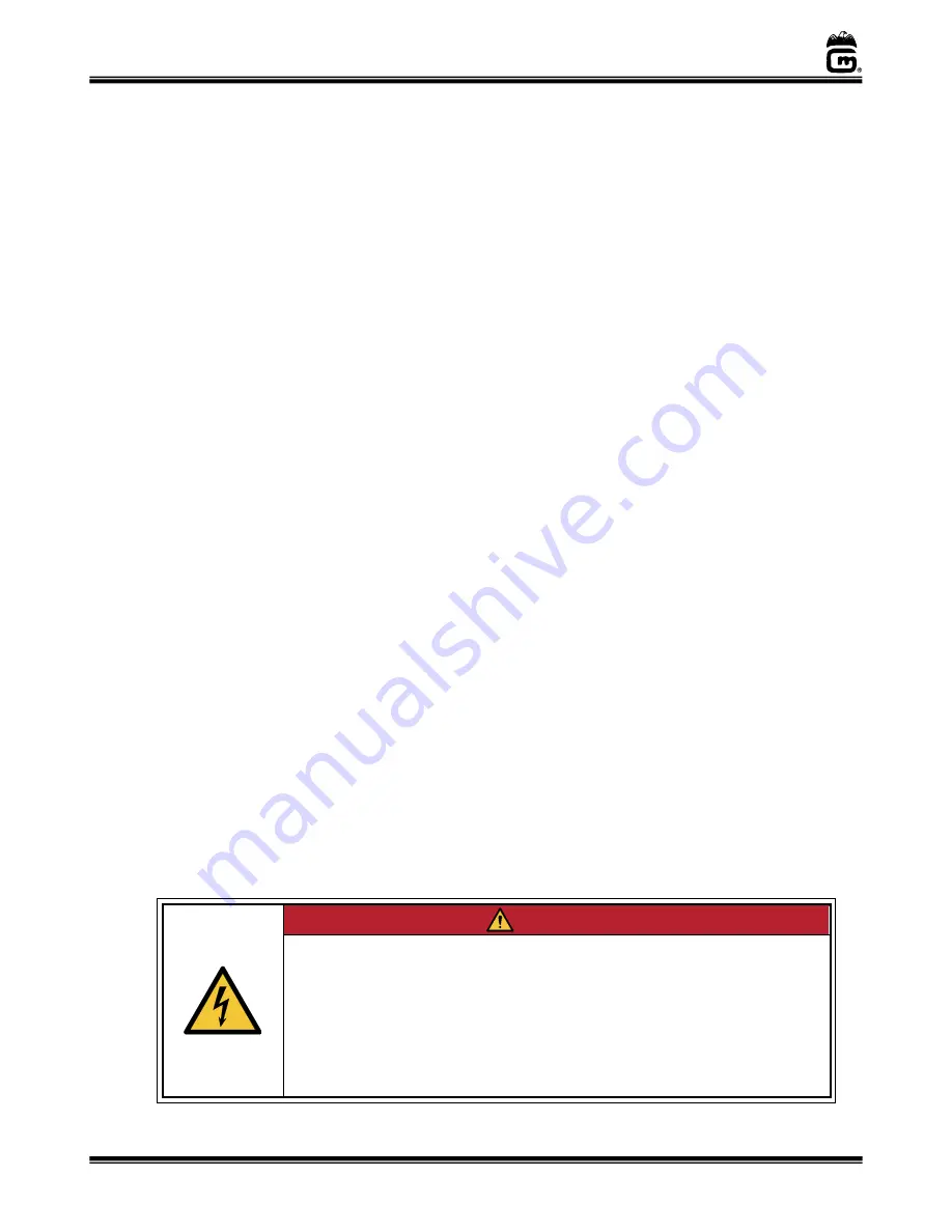
 DANGER


Machine must be properly grounded to prevent electrical shock to personnel. 
Failure to do so could result in serious injury, or death. 
DO NOT immerse any part of this equipment in water.  
DO NOT use excessive water when cleaning. 
Keep cord and plug off the ground and away from moisture. 
Always unplug the equipment before cleaning or servicing. 
Make sure all machine switches are in the OFF position before plugging the 
equipment into the receptacle. 

008_051514 


Содержание Medallion 100 Series

Страница 1: ... 110302 Instruction Manual 10700 Medallion Drive Cincinnati Ohio 45241 4807 USA Grand Twin Grand Pop O Gold Medallion 100 Series For 1XX Series Models beginning with 2848 2860 and 2873 32 oz Pop O Golds 2948 2960 and 2973 52 oz Medallions ...

Страница 2: ...LLAR ADJUSTMENT 23 THE FOLLOWING SECTIONS ARE FOR QUALIFIED SERVICE PERSONNEL ONLY 24 MAINTENANCE INSTRUCTIONS 24 Kettle Circuit Breaker 25 Electronic Temperature Control Domestic 26 Electronic Temperature Control Export 28 ORDERING SPARE PARTS 30 Replacing Broken Glass 31 32 and 52 oz Flat Lid Kettle Assembly Agitator Assembly 34 32 and 52 oz Kettle Bottom Assembly Parts Breakdown 36 Cabinet Inte...

Страница 3: ...rations to this equipment will void the warranty and may cause a dangerous condition This appliance is not intended to be operated by means of an external timer or separate remote control system NEVER make alterations to this equipment Read the Installation Operating and Maintenance Instructions thoroughly before installing servicing or operating this equipment 014_020416 WARNING To avoid burns DO...

Страница 4: ... experience and knowledge unless they have been given supervision or instruction concerning use of the appliance by a person responsible for their safety DO NOT install equipment in an area where a water jet is used Unit to be installed in locations where ambient temperatures are between a minimum of 5 C 41 F and a maximum of 55 C 131 F Unit to be installed in locations where it can be overseen by...

Страница 5: ...ment To order copies of the operator s manual go to gmpopcorn com or write to Gold Medal Products Co 10700 Medallion Drive Cincinnati OH 45241 USA 1 800 543 0862 Model Description The Elite Series Popper has a uni body stainless steel construction Individual popper features vary by model thus images provided throughout the manual are for general model reference only Other features and options Butt...

Страница 6: ...he two casters on the operator controls side have a locking unlocking feature 4 Make sure kettle lead in cord is securely plugged into unit and the locking ring is fully twisted onto the kettle receptacle see image below 29 6 cc Flavacol Measure PN 47681 Incl with 32 oz units and 52 oz units for Flexi Pop 32 oz Corn Cup PN 67905 32 Incl with 32 oz units and 52 oz units for Flexi Pop 18 oz Corn Cup...

Страница 7: ...f this manual The small power cord 6 prong plug is the oil pump harness which supplies power to the oil dispense unit Plug the oil harness into the 6 prong receptacle on the side of the oil unit control box make sure receptacle lock is fully engaged see image below Refer to the Bag in a Box or Bucket Pump Instruction Manual for complete instructions to connect the oil dispense system to the popper...

Страница 8: ...ating the unit see Care and Cleaning section of this manual Side Panel Installation and Removal The base is equipped with removable side access panels If a panel is removed make sure it is reinstalled before unit use Corn Pan Deep Well Corn Bin View 3 Back Pins Used to elevate the Corn Pan for a shallower Corn Bin 3 Front Pins Used to elevate the Corn Pan for a shallower Corn Bin Side Panel Instal...

Страница 9: ...will accept the attachment plug on the machine and must be used reference the Receptacle Wiring Diagram for NEMA 14 50 for receptacle installation instructions EXPORT UNITS 220 230 V 50 60 Hz reference unit Data Plate for Wattage requirement Potential Electrical Variations 220 V 60 Hz Twin Models have two kettles and two plugs one for each side of popper Export units are designed to operate on sin...

Страница 10: ...8 provided with the unit If the receptacle is wired incorrectly the heat elements kettle and other electrical components could be at 208 or 240 V potential instead of the needed 120 V resulting in excessive temperatures in the heat elements i e kettle and possible fire and or damage to electrical components Receptacle Wiring Diagram for NEMA 14 50 120V Units A certified electrician must follow the...

Страница 11: ...le fire and or damage to electrical components Before You Plug In Machine 1 Make sure all machine switches are OFF before plugging equipment into receptacle 2 Make sure wall outlet can accept the grounded plugs where applicable on the power supply cord 3 The wall outlet must have the proper polarity If in doubt have a competent electrician inspect the outlet and correct if necessary 4 DO NOT use a...

Страница 12: ...r to the kettle agitator motor and exhaust blower The Kettle Motor Switch MUST be ON at all times when there is popcorn popped or un popped in the kettle The green switch light ON indicates there is power to the agitator motor and exhaust blower WARMER SWITCH Two position ON OFF lighted rocker switch supplies power to the crisper blower in the corn staging area keeps popcorn fresh and crisp SALT S...

Страница 13: ...d RED OIL DISPENSE PUSH BUTTON PB SWITCH GREEN OIL LIGHT Red Push Button Switch dispenses a predetermined amount of oil into the kettle when pressed The Oil System Master Switch must be ON for the Oil Dispense PB Switch to activate reference the Instruction Manual for the oil dispense unit The Oil Light on the popper will light continuously when oil pump is dispensing During calibration of the oil...

Страница 14: ...ol scoop provided for Flexi Pop use a half scoop Note When using coconut oil be sure the oil is liquid As a check dispense oil into a measuring cup first then use that oil for the first popping cycle 1 Turn all switches ON set Flexi Pop to desired batch size set Salt Sweet Switch to Salt 2 When kettle is ready about 5 8 minutes the Load Dump Light and Beeper if enabled will turn ON 3 Lift kettle l...

Страница 15: ...tle lid and pour in pre measured amount of corn 4 Press the Red Oil Dispense PB Switch to add oil light and beeper will turn OFF in approx 20 seconds 5 Add pre measured amount of Glaze Pop or Sugar when using sugar we recommend using Compound S to help keep kettle clean close lid Caution Do not open kettle lid to add sugar if popping has started as injury may result 6 When the light and beeper com...

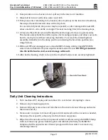
Страница 16: ...mely important to follow all cleaning procedures otherwise parts damage and equipment failure will result The warranty does not cover parts that are damaged due to improper cleaning Daily Kettle Cleaning Instructions Under no circumstances should the kettle be removed from the machine for cleaning 1 Turn the power switch OFF and unplug the unit CAUTION A hot kettle will cause burns if you touch it...

Страница 17: ...ettle into the dump position and swing the hook into position see image below 12 With unit OFF and unplugged use a clean SLIGHTLY damp cloth wring ANY EXCESS water from cloth before use and wipe the kettle lead cord clean DO NOT get moisture into the kettle lead in cord severe damage will result 13 After kettle cleaning check to be sure the crossbar fasteners are securely tightened Daily Unit Clea...

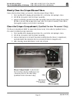
Страница 18: ...aned on a daily basis and the two internal filters should be cleaned weekly to maintain maximum efficiency Follow the steps below for proper filter cleaning Step 2 Weekly Filter Cleaning Loosen the 2 screws on the filter cover plate on the ceiling inside the popper Remove the cover the Bag Filter and the 2 Mesh Filters Step 3 Clean the bag filter and mesh filters in warm soapy water then rinse Let...

Страница 19: ...partment Qualified Service Personnel Only The blower compartment MUST be inspected cleaned every 3 4 months by Qualified Service Personnel to maintain proper operation 1 Turn machine OFF unplug unit and allow it to cool before attempting to clean 2 Lift off the corn pan to view the blower assembly 3 Remove the blower cover and if required carefully clean the blower compartment and underneath the e...

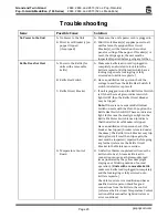
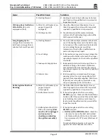
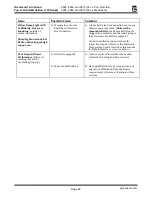
Страница 20: ... is ON but the small green indicator switch light is OFF then the Kettle Circuit Breaker may be tripped Note If there is not a separate Kettle Heat Switch on units with the Flexi Pop option the Kettle Heat Switch will NOT have an indicator light In this case the small green light on the Kettle Stir Motor Switch is used to indicate that the Kettle Circuit Breaker is tripped Have a qualified service...

Страница 21: ...ualified electrician C Inadequate Supply Lines C Inadequately sized electrical supply lines in addition to being a fire hazard would also prevent the kettle from reaching the proper operating temperature Check with a qualified electrician D Inferior Corn D Inferior quality corn would result in longer popping cycles Use only top quality hybrid popcorn from reputable suppliers Even then if you let y...

Страница 22: ...issue Units with a removable kettle make sure kettle lead is plugged in completely and the locking ring is fully screwed onto kettle receptacle Contact qualified service personnel for inspection repair reference the Electronic Temperature Control section of this manual for light indicators or error condition Poor Crisper Blower Performance Blower is working but air not circulating properly A Filte...

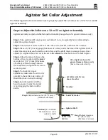
Страница 23: ...ance between the kettle cook surface and the shaft reference image shown Once adjusted re tighten the set screw in the set collar above the crossbar to secure shaft in place Step 4 Adjust clearance between the bottom of the crossbar and the lower set collar to 1 32 1 mm thickness of a dime reference image shown Once adjusted re tighten set screw to secure in place Step 5 To check for proper adjust...

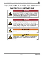
Страница 24: ...NOT use a water jet or excessive water when cleaning 008_012221 DANGER Improper installation adjustment alteration service or maintenance can cause property damage injury or death Any alterations to this equipment will void the warranty and may cause a dangerous condition This appliance is not intended to be operated by means of an external timer or separate remote control system NEVER make altera...

Страница 25: ...he Kettle Circuit Breaker is tripped For hanging kettle machines On Standard Poppers the Kettle Circuit Breaker is located under the dome An additional cover must be removed to reset the circuit breaker On PopClean Poppers the side dome panel must be removed to access the circuit breaker located on the vertical controls panel in the dome interior reference images below For pedestal mounted kettle ...

Страница 26: ...control and one for fixed high limit There are no mechanical thermostats in this kettle There are 4 factory settings on the control see descriptions below If needed adjustments may be made to the Kettle Dump and Audible Signal to Dump The remaining settings are factory set for the unit DO NOT adjust 1 Control Set Point Temperature This is factory set DO NOT adjust 2 The Overshoot circuit is tuned ...

Страница 27: ...ill indicate one of two thermocouple error conditions Reversed Probe Indicates the thermocouple probe has been connected in reverse The yellow leads must go to the positive terminals If the kettle heats for a short time and then stops and the red Probe LED light is ON then one or both Thermocouple is wired in reverse Check TC A and TC B make sure the yellow leads go to the positive terminals Open ...

Страница 28: ...control and one for fixed high limit There are no mechanical thermostats in this kettle There are 4 factory settings on the control see descriptions below If needed adjustments may be made to the Kettle Dump and Audible Signal to Dump The remaining settings are factory set for the unit DO NOT adjust 1 Control Set Point Temperature This is factory set DO NOT adjust 2 The Overshoot circuit is tuned ...

Страница 29: ...ill indicate one of two thermocouple error conditions Reversed Probe Indicates the thermocouple probe has been connected in reverse The yellow leads must go to the positive terminals If the kettle heats for a short time and then stops and the red Probe LED light is ON then one or both Thermocouple is wired in reverse Check TC A and TC B make sure the yellow leads go to the positive terminals Open ...

Страница 30: ...nly approved replacement parts when servicing this unit 3 When ordering please include part number part name and quantity needed 4 Please include your model number serial number and date of manufacture located on the machine nameplate data plate with your order 5 Address all parts orders to Parts Department Gold Medal Products Co 10700 Medallion Drive Cincinnati Ohio 45241 4807 or place orders by ...

Страница 31: ...5 125 125 125 1 Turn machine OFF unplug unit and allow it to cool before attempting to replace glass 2 Remove all loose pieces of broken glass 3 Pull out Magnetic Clip located above glass panel in cabinet interior see image below The magnetic clip is used for shipping purposes only holds glass in place during transit 4 Remove all rigid glass channels from around glass to be replaced set channels a...

Страница 32: ...efore installing 7 Complete Agitator Assembly Includes Lids To install Nut Retainer Slightly bend tabs down Once bolts are tightened into block fully bend each tab against flat side of head 19 20 21 18 16 14 15 22 17 23 52 oz Complete Agitator Assembly shown includes Lids Spacer increases height of shaft when bearing does not rest at least 3 16 into gear block 11 12 10 13 9 See Spur Gear Parts Lis...

Страница 33: ...38 106038 106038 9 BEARING CAM FOLLOWER 61225 61225 61225 61225 10 SPACER used to increase shaft height when Cam Follower Bearing does not rest at least 3 16 into Gear Block 106035 106035 106035 106035 11 SPUR GEAR KIT Inclds 2 gears w set screws Always replace Agitator Spur Gear Kettle Drive Gear as a set 41380K 41380K 41380K 41380K 12 SET SCREW 1 4 20 X 3 16 47751 47751 47751 47751 13 WOODRUFF K...

Страница 34: ...p Kettles 7 4 1 2 3 5 6 Apply Loctite 246 before installing Complete Agitator Assembly Includes Lids 52 oz Complete Agitator Assembly shown includes Lids Spacer increases height of shaft when bearing does not rest at least 3 16 into gear block 10 11 9 12 8 See Spur Gear Parts List note General 52 oz Flat Lid Kettle views shown for parts reference 2127EX 18 16 13 14 20 15 19 17 Kettle Lead is hard ...

Страница 35: ...stalling 67947 7 LID AGITATOR ASSY Complete Assy 41775NH 41775 48961 8 BEARING CAM FOLLOWER 61225 61225 61225 9 SPACER used to increase shaft height when Cam Follower Bearing does not rest at least 3 16 into Gear Block 106035 106035 106035 10 SPUR GEAR KIT Inclds 2 gears w set screws Always replace Agitator Spur Gear Kettle Drive Gear as a set 41380K 41380K 41380K 11 SET SCREW 1 4 20 X 3 16 47751 ...

Страница 36: ...reakdown Reference 32 oz Parts List or 52 oz Parts List for specific Kettle Model Kettle Shell Bottom View Junction Box Interior View 17 18 16 15 14 20 21 22 23 16 19 20 21 52 oz Element view shown General images shown for parts reference only Reference wire diagram shipped with popper for wiring 3 4 1 2 5 Form a tab UP on flat of nut to retain nut position Form tab DOWN 6 7 9 8 11 12 13 10 ...

Страница 37: ...equired 41491 41491 41491 41491 6 HEX NUT 1 4 20 16 required 74133 74133 74133 74133 7 1 4 20 X 1 25 SET SCREW 69140 69140 69140 69140 8 NUT RETAINER 50190 50190 50190 50190 9 1 4 20 RND TOP SQ NUT 69156 69156 69156 69156 10 RETAINING NUT 41434 41434 41434 41434 11 HEAT ELEMENT 1050W 48651 48651 48651EX 48651EX 12 TUBULAR ELEMENT 1800W 48650 48650 48650EX 48650EX 13 TUBULAR ELEMENT 1000W 41536 415...

Страница 38: ...TLE 56118 56118 56118 5 ELEMENT CLAMP 52 oz Medallion 68780 68780 68780 6 HEX NUT 1 4 20 74133 74133 74133 7 1 4 20 X 1 25 SET SCREW 69140 69140 69140 8 NUT RETAINER 50190 50190 50190 9 1 4 20 RND TOP SQ NUT 69156 69156 69156 10 RETAINING NUT 41434 41434 41434 11 TUBULAR ELEMENT 1050W 48651 48651 48651EX 12 TUBULAR ELEMENT 1800W 48650 48650 48650EX 13 HEAT ELEMENT 2700W 82597 82597 82598 14 KETTLE...

Страница 39: ... 39 gmpopcorn com Updraft Cabinet Exterior Parts Breakdown See Replacing Glass section 7 3 4 1 2 Panel opposite side of sign See Sign Option section General image used for parts reference models may vary 5 Top Dome Cover 16 15 14 13 10 11 12 17 18 19 21 20 Door and Caster Hardware See Kettle section 6 9 24 23 Side Panel View 22 8 ...

Страница 40: ...5309 GLASS CHAN 43 125 for top bottom of front glass 115314 GLASS CHAN 26 1 8 for top bottom of front glass 61036 GLASS CHAN 32 312 for top bottom of front glass 115312 9 UNIVERSAL DOOR LG POPPER 120323 120323 120323 10 FLUSH MOUNT HANDLE order 1 for each door 82698 82698 82698 11 8 32 X 3 8 PAN HD PH M S 12389 12389 12389 12 8 32 HEX NUT ESLOK S S 22070 22070 22070 13 MALE HINGE SHORT LEFT 41349 ...

Страница 41: ...P inclds set screw kettle retainer latch and knob 49505 48908 49505 48908 7 10 32 X 1 SOC SET CUP PT 41448 41448 41448 41448 8 KETTLE RETAINER 43426 43426 43426 43426 9 CLEAN IN PLACE LATCH 41618 41618 41618 41618 10 KNOB GEAR LOCK 12319 12319 12319 12319 11 SPUR GEAR KIT Inclds 2 gears w set screws Always replace Agitator Spur Gear Kettle Drive Gear as a set 41380K 41380K 41380K 41380K 12 SET SCR...

Страница 42: ...2743 42743 5 SWITCH LIGHTED ROCKER GR 42798 42798 6 SWITCH ROCKER DPDT GOLD 55440 55440 7 ROCKER SWITCH COVER 48786 48786 8 PILOT LT 125V GRN NEON 48660 48660EX 9 SWITCH OIL PUMP 41031 41031 10 PILOT LIGHT AMBER 55039 55039EX 11 PILOT LIGHT BLUE 55473 55473 12 FILTER COVER ASSEMBLY 41934 41934 13 OIL MIST FILTER 41169 41169 14 5 LAYER GREASE FILTER 1 filter 2 required per blower box 41250 41250 Al...

Страница 43: ...15465 115466 2 CORN SCRN INS W HNDL 375 115422 115422 115422 3 CORN SCRN INS W HNDL 5 115423 115423 115423 4 TOP PLATE 63550 63550 63550 5 8 32 X 3 8 PHIL PAN HEAD 87515 87515 87515 6 FILTER AND GUARD ASSY 63707 63707 63707 7 8 32X5 8 FL HD PH MS 20067 20067 20067 8 8 32 SERRATED FLANGE NUT 61151 61151 61151 Blower Box Exterior View Under Corn Pan Corn Pan View 5 4 7 8 6 Mushroom Corn Screen Inser...

Страница 44: ...7124 7 WASHER 8 INTERNAL TOOTH 74150 74150 8 HEX NUT 8 32 STAINLESS 89129 89129 9 BLOWER includes fasteners and screen 61123 61124 10 HEAT ELEMENT 800W 61128 61135 11 U CLIP 55215 55215 12 HEATER CLAMP 61133 61133 13 HEATER MOUNT 61134 61134 14 8 32 X 1 2 PH PAN W SEMS 47124 47124 15 8 32 X 1 2 PHIL PN M S SS 42226 42226 16 8 32 SERRATED FLANGE NUT 61151 61151 17 THERMOSTAT MOUNTING BRACKET 55500 ...

Страница 45: ... only parts may vary by model 25 26 Glides sold in pairs RH and LH 34 33 35 Connects to Oil Unit reference Oil Unit Manual 24 23 22 21 31 32 27 29 30 28 7 Jump Bar used on terminal blocks of select Models only reference Wire Diagram 20 19 17 36 37 12 3 1 2 5 6 4 15 10 11 16 17 Strain Relief 6 Pin Oil Disp Power Cord GND Fasteners Wire Harness to Corner Post Strain Relief Power Supply Cord Strain R...

Страница 46: ...rness 41735 41735 17 WIRE HARNESS OIL PUMP 41499 41499 18 HOLE PLUG 118262 118262 19 5 POSITION WIRE CONNECTOR 55244 55244 20 3 POSITION WIRE CONNECTOR 55245 55245 21 8 32X1 FL HD PH MS 20068 20068 22 MAGNET USES 8 FLT HD SC 50013 50013 23 MAGNET SPACER 68115 68115 24 HEX NUT 8 32 ESLOK 74146 74146 25 ALUM OIL LINE TUBING 41047 41047 26 FOIL ELEMENT 8 WATT wraps oil line 41640 41640EX 27 OLD MAID ...

Страница 47: ...BLE BLOWER EXHAUST 62845 62845EX 7 EXHST BLOWER PLUG CORD 47199 47199 47199 47199 8 EXHAUST BLOWER 48018 48037 48018 48037 9 TEMPERATURE CONTROL 41001 41001 41001 41001 10 CIRCUIT BREAKER 47364 48659 47364 48659 11 CIRCUIT BREAKER for Kettle 55223 55225 55223 55225 12 K T C SHIELDED EXT WIRE 55051 55051 55051 55051 13 TERMINAL BLOCK 8 POS 47208 47208 47208 47208 14 ALUM OIL LINE TUBING 41047 41047...

Страница 48: ...Pop 46081 3 RELAY DPST NO 48590 48590EX 4 RELAY DPDT 48645 48645EX 5 IEC CONTACTOR 4 POLE 30A 55562 6 CONTACTOR IEC 40 AMP 48912 7 CONTACTOR IEC 32A 120V 48945 8 RELAY POWER 240V DPDT 49858 Ventilation Control Components V Models ONLY 9 TIMER OFF DELAY SPDT 55157 10 RELAY SOCKET 2 POLE 89085 11 8 PIN SOCKET 79141 12 RELAY DPDT 120VAC 55036 Dome interior for Single Kettle Model shown for general pa...

Страница 49: ...20 8 6 32 X 3 8 PH PAN HD M S 38087 9 WASHER 6 INTERNAL TOOTH 76188 10 6 32 HEX NUT ZINC PLATED 38005 11 LED STRIP COOL WHITE 55379 12 BUSHING SNAP 500 IN 47236 13 6 32 X 5 8 PH PAN HD M S 87000 14 6 32 GRIP NUT ZINC PLATED 47517 15 POWER SUPPLY 24VDC 60W 55586 16 5 POSITION WIRE CONNECTOR 55245 17 3 POSITION WIRE CONNECTOR 55244 18 COVER 30 NEON SIGN 67418 19 LED POPCORN SIGN 69707 20 MOLDED PLUG...

Страница 50: ...WARNING LABEL CORD 68720 68720 9 52OZ CORN CUP ASSEMBLY 17757 52 17757 52 10 CORN CUP ASSY 32 OZ 67905 32 67905 32 11 CORN CUP ASSY 18 OZ 67905 18 67905 18 12 MEASURE 1 4 CUP 47169 47169 13 MEASURE 2 TBS 29 6cc 47681 47681 14 FLAVACOL CONT WELDMENT 41752 41752 15 PERF JET SCOOP REGULAR RH 2072 2072 16 TUBE BRUSH 47380 47380 17 RECPT 30A 125 250 VOLT 82208 18 RECEPTACLE 50AMP 82920 19 RECEPTACLE CO...

Страница 51: ...848 2860 and 2873 32 oz Pop O Golds Pop O Gold Medallion 100 Series 2948 2960 and 2973 52 oz Medallions Page 51 gmpopcorn com Wiring Diagram For wiring information please reference the Wiring Diagram shipped with the popper ...

Страница 52: ... ALL OTHER OBLIGATIONS OR LIABILITIES ON OUR PART INCLUDING THE IMPLIED WARRANTY OF MERCHANTABILITY THERE ARE NO WARRANTIES WHICH EXTEND BEYOND THE DESCRIPTION ON THE FACE HEREOF In no event shall Gold Medal Products Co be liable for special incidental or consequential damages No claim under this warranty will be honored if the equipment covered has been misused neglected damaged in transit or has...

Отзывы: